PIR sensor need help

Thread Starter

ericyeoh

Joined Aug 2, 2009
58
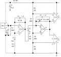
Guys i still dun understand the band pass design in below attrached circuit.

the 1st IC1A and IC1B opamp hv , FL and FH at 1.59hz.

FH = (1/[2(pie) 10mic x 10K]) = 1.59hz
FL = (1/[2(pie) 0.1mic x 1M]) = 1.59hz

how come both cut off frequency at 1.59hz? if this is the case, the bandwidth =0 hz?

Please help me pls, i'm lost
 

Attachments

wayneh

Joined Sep 9, 2010
18,104
I'm no expert on filters, but they're not like a brick wall. Wouldn't that arrangement give a peak transmittance at 1.59 Hz and taper off on both sides?
 

GetDeviceInfo

Joined Jun 7, 2009
2,271
But as i studied about PIR sensor, the radiance produce by human carry around 0.1-10hz with 1mV-20mV waveform.
The IR radiation is not what this circuit is about. These sensors are typically dual (opposing) elements. The circuit senses a rate change across the elements. The filtering aspects of the circuit are designed around this rate of change. Motion from a radiant object has a very low frequency compared to circuit noise, which the latter must be filtered out.
 

wayneh

Joined Sep 9, 2010
18,104
wayneh, i cann;t catch what u meant. Could you please explain further?
Combining a low pass and a high pass filter gives you a band-pass filter. Frequencies too high or too low are attenuated. An audio amplifier is sort of a band-pass filter, since it allows frequencies in the 20-20kHz range to pass, but not much outside that range. Of course that's a 1000X range, quite wide and a challenge to achieve.

In your case the band allowed to pass is centered at 1.59Hz, and the width of the band allows a range of nearby frequencies to also pass. But frequencies too high or low - things not related to a human - are filtered out.
 
Top