Facebook
 Google
 GitHub
 Linkedin
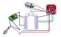
Hey everyone. I'm working on a school project and would truly appreciate some help with the wiring diagram.
ESP32 Dev Module (30-pin, USB-C version)
NPN NO Inductive Proximity Sensor (12V, 3-wire type: brown +, blue –, black output)
Optocoupler (PC817 or similar)
L298N Motor Driver module
DC Motor (powered separately from 12V source)
External 12V power supply for motor and sensor
USB for powering ESP32
I want the NPN proximity sensor to detect a metal, send its signal through an optocoupler, and then safely trigger a GPIO pin on the ESP32 (3.3V logic). When the ESP32 detects the sensor is triggered, it should stop the motor through the L298N motor driver. I understand that the proximity sensor supplies +12V, so I cannot connect it directly to the ESP32. The optocoupler protects the ESP32, but I am unsure how to correctly wire the resistors (if any are needed), pull-ups (if any are needed), and grounds when using both sensor and motor driver.
My questions:
Can i safely wire the NPN sensor to the optocoupler and then from the optocoupler to the ESP32 board without a resistor between the optocoupler and ESP32? I've watched some videos that say it is not necessary as these two circuits are separate.
Is my logic okay with this? Sensor detects → optocoupler closes → ESP32 reads LOW on pin → motor stops
Here is the code that I want to test for the system:
C-like:
const int sensorPin = 21;      // Signal coming from optocoupler transistor

const int motorEnable = 25;    // PWM pin to control motor speed (ENA on L298N)

const int motorIn1 = 26;       // IN1 on L298N

const int motorIn2 = 27;       // IN2 on L298N


void setup() {

  Serial.begin(115200);


  pinMode(sensorPin, INPUT_PULLUP); // using internal pullup for now


  pinMode(motorIn1, OUTPUT);

  pinMode(motorIn2, OUTPUT);


  ledcSetup(0, 5000, 8); // Channel 0, freq 5kHz, resolution 8-bit

  ledcAttachPin(motorEnable, 0);


  // Motor forward

  digitalWrite(motorIn1, HIGH);

  digitalWrite(motorIn2, LOW);

  ledcWrite(0, 255); // Full speed

}


void loop() {

  int sensorValue = digitalRead(sensorPin);


  if (sensorValue == LOW) {

    Serial.println("Metal detected - stopping motor!");

    ledcWrite(0, 0);

  } else {

    Serial.println("No metal detected - motor running");

    ledcWrite(0, 255);

  }


  delay(1000);

}
Last edited by a moderator: