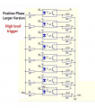
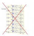
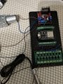
Everything works and the sensors are detecting metal and the ESP32 is registering it, but I am having one problem. I wired all of the "In"s to one common anode and when one sensor is triggered both lane 1 and 2 LED lights up. I included a diagram of how I wired it with the black wires to each ground and the positive wire across the optocouplers.. Why does one sensor trigger both lanes using this method and how do I fix it?
On the input side, output side or both?
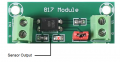
That's not the same module shown before.
I would check the solder connections on the input and output wiring, possible shorts.
On the input side, output side or both?
That's not the same module shown before.
I would check the solder connections on the input and output wiring, possible shorts.
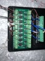
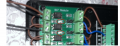
The input wiring looks OK from my perspective although not focused very well.
You are saying those two LEDs in the red circles are both lighting up regardless of which sensor is activated?
The input wiring looks OK from my perspective although not focused very well.
You are saying those two LEDs in the red circles are both lighting up regardless of which sensor is activated?
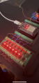
Correct. When I activate one circuit, it appears the rest are activated as well. But I want them to activate individually. Does the LED indicate a complete circuit or does it only indicate power is being supplied? I dont understand how they all light up if there is no ground for each of them.
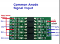
That board is wired different and not the same board shown in post #8.
It has a common negative input which explains why all the inputs are lit up.
That board is triggered by a positive signal on the anode and won't work unless modified.
That board is wired different and not the same board shown in post #8.
It has a common negative input which explains why all the inputs are lit up.
That board is triggered by a positive signal on the anode and won't work unless modified. View attachment 359868
So I could essentially swap to a PNP sensor run the black wires to the "IN"s and ground the other lanes to common ground and that would work for this board?
So I could essentially swap to a PNP sensor run the black wires to the "IN"s and ground the other lanes to common ground and that would work for this board?
Correct the output from the PNP sensor would connect to where those brown jumpers are currently.
If you want I believe that board can be modified by cutting that common pc trace between all the ground terminals.
That will isolate each ground input.
EDIT: Not feasible.
Thanks.
My previous suggestion won't work because the way the board is made.
This mod will work but the LED is removed.
I believe your best option and least expensive is to replace the PC817 module rather then replacing the sensors.
Thanks.
My previous suggestion won't work because the way the board is made.
This mod will work but the LED is removed.
I believe your best option and least expensive is to replace the PC817 module rather then replacing the sensors. View attachment 359870
With the PNP sensors the common ground is not a problem.
Actually this PC817 module you have will work fine for PNP sensors.
But isn't it less expensive to just replace the module since you already have two NPN sensors?
With the PNP sensors the common ground is not a problem.
Actually this PC817 module you have will work fine for PNP sensors.
But isn't it less expensive to just replace the module since you already have two NPN sensors?
I am eventually going to expand this project to use more than 2 sensors and will probably change the sensors from NPN NO to PNP NC. I will have to adjust the code a bit but that is no worries should be simple. Thank you! I am excited to try this.
Good news: the new sensors work and control each lane individually.
Kind of good news: When I run the code I get a constant motor signal even when bringing the sensor to a low state (triggering the sensor with metal). Ill post the code below that I am using. I have the grnd shared with the sensor and the motor relay and ESP32. Not sure where to go from here.. Seems to be a circuit issue at this point. Also, the motor is running completely independent of the sensor. When I unplug the Pin1 of the motor relay the motor stops running. And when I touch D15 to ground on the ESP32, the motor stops. So this seems to be a sensor to optocoupler issue.
const int sensorPin = 15;
const int motorPin = 26;

 Facebook
 Google
 GitHub
 Linkedin