Pinout of Ethernet connector RJ45

Thread Starter

engr_david_ee

Joined Mar 10, 2023
358
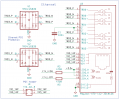
The PCB mount RJ45 has two pinout sides. One pinout is for the cable, and other pinout for the PCB. The pinout on the cable side is standard consisting of eight pins and does not need to be mentioned in the datasheets of the Ethernet RJ45 connector.

But the pinout of these connector for the PCB could be different, right ? I guess they can be different. I don't understand why it is not mentioned in most datasheets of the Ethernet RJ45 connectors.
 

Jon Chandler

Joined Jun 12, 2008
1,560
RJ45 jacks come is a variety of styles:
● 8 conductor jack ± shield
● 8 conductor jack with LEDs ± shield
● 8 conductor jack with magnetics ± shield
● 8 conductor jack with magnetics and LEDs ± shield

Beyond that, manufacturers and different series all have different footprints. There are some common footprints, but make no assumptions for a particular part.
 

Thread Starter

engr_david_ee

Joined Mar 10, 2023
358
RJ45 jacks come is a variety of styles:
● 8 conductor jack ± shield
● 8 conductor jack with LEDs ± shield
● 8 conductor jack with magnetics ± shield
● 8 conductor jack with magnetics and LEDs ± shield

Beyond that, manufacturers and different series all have different footprints. There are some common footprints, but make no assumptions for a particular part.
This is correct.

Thanks for sharing this info.

But the connector pinout for the cable has to be the same in all different types of RJ45 connectors, right ? As there are four pairs in the cable and the pin order on the connector to attach cable has to be the same in all different types of RJ45 connectors.
 

Thread Starter

engr_david_ee

Joined Mar 10, 2023
358
Please share the connector part number.

How connector pins 1 to 8 are mapped to signal names (or how they are connected to the differential pais in the cable) usually not mentioned in the datasheets. I guess they are mapped in standard way.
 

drjohsmith

Joined Dec 13, 2021
1,548
Please share the connector part number.

How connector pins 1 to 8 are mapped to signal names (or how they are connected to the differential pais in the cable) usually not mentioned in the datasheets. I guess they are mapped in standard way.
Uhm
The ethernet connector , is just pin numbers 1 to 8
The socket data sheet should show you pins 2 to 8 for the ethernet ,
Other pins in the socket can be for shield connection or LEDs .
Find the board connectors data sheet !
 

eetech00

Joined Jun 8, 2013
4,704
This is correct.

Thanks for sharing this info.

But the connector pinout for the cable has to be the same in all different types of RJ45 connectors, right ? As there are four pairs in the cable and the pin order on the connector to attach cable has to be the same in all different types of RJ45 connectors.
Yes…they have to be the same to meet Ethernet standards. Otherwise they might not work with devices that do meet the ethernet standard. Ethernet cable standards are specific.

you can call your wiring “proprietary” then it can be anything you want.
 

Thread Starter

engr_david_ee

Joined Mar 10, 2023
358
Thanks. The schematics shown in #8 for the connector from Belfuse has 16 pins on the PCB side to solder.

Here is the detail.
Pin 1 to Pin 12: Four differential pairs (TRD1+/TRD1- , ..... TRD4+/TRD4-) and four CT pin.
Pin 13 and Pin 14: LED 01
Pin 15 and Pin 16: LED 02

Notice the pins order, TRD1+/TRD1- is connected to Pin 11 and Pin 12 in Belfuse part.

I would to compare this side of the connector that we solder on the PCB with the following schematic available in attachment.

The part number is ARJM11B1-502-AB-EW2-2.
The pinout detail on PCB side is below.
Pin 1 to Pin 10: Four differential pairs (TRD1+/TRD1- , ..... TD4+/TD4-) and two CT pin.
Pin 11 and Pin 12: Left LED
Pin 12 and Pin 14: Right LED

Notice the pins order, TD1+/TD1- is connected to Pin 1 and Pin 2 in ARJM11B1-502-AB-EW2-2.

This shows that the two parts have different pinout on the PCB side.

I was wondering about this difference in pinout and would like to discuss in this post.

The other side (RJ45) of both parts (the cable side) have the same pinout which is standard I think.
 

Attachments

Last edited:

Thread Starter

engr_david_ee

Joined Mar 10, 2023
358
One last point I would like to ask what is the role of filer and magnetics in RJ45 connectors ?

Some RJ45 come with such filter and magnetics, not all.

The presence of transformers in RJ45 indicate that the signal propagating through RJ45 connector with filter and magnetics to the cable is analog, i.e. not digital. It must be analog, right ?
 

drjohsmith

Joined Dec 13, 2021
1,548
One last point I would like to ask what is the role of filer and magnetics in RJ45 connectors ?

Some RJ45 come with such filter and magnetics, not all.

The presence of transformers in RJ45 indicate that the signal propagating through RJ45 connector with filter and magnetics to the cable is analog, i.e. not digital. It must be analog, right ?
Space . / Convenience
It's nominaly cheaper to purchase individual parts , dumb socket , transformer , filter parts .
But by time you have designed the board , Afixed the parts , paid for multiple stock lines on the pick and place machine , and size , combined single item often wins out.
 

nsaspook

Joined Aug 27, 2009
16,249
One last point I would like to ask what is the role of filer and magnetics in RJ45 connectors ?

Some RJ45 come with such filter and magnetics, not all.

The presence of transformers in RJ45 indicate that the signal propagating through RJ45 connector with filter and magnetics to the cable is analog, i.e. not digital. It must be analog, right ?
Analog or digital is circuit design notation for the desired effect, EM energy doesn't care about the design name, only signal transmission properties as it propagates. It's all about frequency response.

https://www.molex.com/en-us/products/connectors/modular-connectors/rj45-with-magnetics

Magnetic Jacks are advanced RJ45 connectors with integrated magnetics that filter common-mode noise, protect PHY chips, provide DC isolation and reduce mode conversion. Designed for high-speed data transmission, these Magnetic Jacks support higher power delivery over Ethernet while ensuring reliable connectivity and robust protection against electromagnetic interference (EMI).
 
Top