 Facebook
 Google
 GitHub
 Linkedin
Hello Everyone,
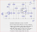
I'm new to this website and the forum. I've been doing a DIY project in which I need all of your help. I want to make a simple Piezo trigger switch which lights up an LED only when it is been striked. P.S-It should be a simple circuit,the schematics you may provide should be a user-friendly one,i.e,no use of symbols because i cant understand them.So,please use the image of the objects as it is in the schematics(like the image attached).Also,please do not give any suggestion to use an arduino(to make it simpler and cheaper). Also,I've attached an image.Will the image work if its female jack is connected to a male jack connected with a piezo sensor?Please Help me.
Thanks
Attachments
-
 7.7 KB Views: 206

")


