 Facebook
 Google
 GitHub
 Linkedin
I've made it volatile variableJust for a test, declare Result3 as volatile unsigned char. It may be that the compiler knows you are not doing anything with Result3 so there isn't any reason to generate the code. Sometimes XC8 is a little too aggressive that way. Declaring Result3 as 'volatile' tells the compiler to leave it alone. You can also look at the disassembler listing to see what code it actually generated, too.
C:
//
#define _XTAL_FREQ 20000000     // crystal 20MHz

// PIC18F45K80 Configuration Bit Settings
// CONFIG1L
#pragma config RETEN = ON       // VREG Sleep Enable bit (Ultra low-power regulator is Enabled (Controlled by SRETEN bit))
#pragma config INTOSCSEL = LOW  // LF-INTOSC Low-power Enable bit (LF-INTOSC in Low-power mode during Sleep)
// SOSCSEL = No Setting
#pragma config XINST = OFF      // Extended Instruction Set (Disabled)
// CONFIG1H
#pragma config FOSC = HS2       // HS oscillator (high power, 16 MHz-25 MHz
#pragma config PLLCFG = OFF     // PLL x4 Enable bit (Disabled)
#pragma config FCMEN = OFF      // Fail-Safe Clock Monitor (Disabled)
#pragma config IESO = OFF       // Internal External Oscillator Switch Over Mode (Disabled)
// CONFIG2L
#pragma config PWRTEN = ON      // Power Up Timer (Enabled)
#pragma config BOREN = OFF      // Brown Out Detect (Disabled in hardware, SBOREN disabled)
#pragma config BORV = 0         // Brown-out Reset Voltage bits (3.0V)
#pragma config BORPWR = LOW     // BORMV Power level (BORMV set to low power level)
// CONFIG2H
#pragma config WDTEN = OFF      // Watchdog Timer (WDT disabled in hardware; SWDTEN bit disabled)
#pragma config WDTPS = 1        // Watchdog Postscaler (1:1)
// CONFIG3H
#pragma config CANMX = PORTC    // ECAN Mux bit (ECAN TX and RX pins are located on RC6 and RC7, respectively)
#pragma config MSSPMSK = MSK5   // MSSP address masking (5 bit address masking mode)
#pragma config MCLRE = ON      // Master Clear Enable (MCLR Enabled, RE3 Disabled)
// CONFIG4L
#pragma config STVREN = OFF     // Stack Overflow Reset (Disabled)
#pragma config BBSIZ = BB1K     // Boot Block Size (1K word Boot Block size)
// CONFIG5L
#pragma config CP0 = ON         // Code Protect 00800-01FFF (Enabled)
#pragma config CP1 = ON         // Code Protect 02000-03FFF (Enabled)
#pragma config CP2 = ON         // Code Protect 04000-05FFF (Enabled)
#pragma config CP3 = ON         // Code Protect 06000-07FFF (Enabled)
// CONFIG5H
#pragma config CPB = ON         // Code Protect Boot (Enabled)
#pragma config CPD = ON         // Data EE Read Protect (Enabled)
// CONFIG6L
#pragma config WRT0 = ON        // Table Write Protect 00800-01FFF (Enabled)
#pragma config WRT1 = ON        // Table Write Protect 02000-03FFF (Enabled)
#pragma config WRT2 = ON        // Table Write Protect 04000-05FFF (Enabled)
#pragma config WRT3 = ON        // Table Write Protect 06000-07FFF (Enabled)
// CONFIG6H
#pragma config WRTC = ON        // Config. Write Protect (Enabled)
#pragma config WRTB = ON        // Table Write Protect Boot (Enabled)
#pragma config WRTD = ON        // Data EE Write Protect (Enabled)
// CONFIG7L
#pragma config EBTR0 = ON       // Table Read Protect 00800-01FFF (Enabled)
#pragma config EBTR1 = ON       // Table Read Protect 02000-03FFF (Enabled)
#pragma config EBTR2 = ON       // Table Read Protect 04000-05FFF (Enabled)
#pragma config EBTR3 = ON       // Table Read Protect 06000-07FFF (Enabled)
// CONFIG7H
#pragma config EBTRB = ON       // Table Read Protect Boot (Enabled)
// #pragma config statements should precede project file includes.
// Use project enums instead of #define for ON and OFF.

#pragma warning disable 520

#include <xc.h>

unsigned char Result1;
unsigned char Result2;
volatile unsigned char Result3;
unsigned char Result4;

// The code should set the R/W bit according to its function
#define SLAVE_ADDRESS        0x90         //I2C slave address of ADS1115 (8 bit format)
#define Word_Address        0x01         // Points to Config register


#define LCD_RS              LATBbits.LATB4
#define LCD_TRIS_RS         TRISBbits.TRISB4
#define LCD_RW              LATBbits.LATB5
#define LCD_TRIS_RW         TRISBbits.TRISB5
#define LCD_E               LATBbits.LATB6
#define LCD_TRIS_E          TRISBbits.TRISB6

#define  LCDPORT            LATD
#define  LCDTRISD           LATD

void Port_Initialized (void);
void WriteNibble(unsigned char command);
void WaitLCDBusy(void);
void WriteCommand(unsigned char command);

void Port_Initialized (void)
{
// LATx registers
    LATA =  0x00;
    LATB =  0x00;
    LATC =  0x00;
    LATD =  0x00;
    LATE =  0x00;

//  TRISx registers
    TRISA = 0x00;      // All are output, Unused
    TRISB = 0x00;      // all are output, Unused
    TRISC = 0x18;      // Slave SDA and CLOCK
    TRISD = 0x00;      // LCD
    TRISE = 0x00;      // All are output, Unused

    ANCON0 = 0x00;     // set to digital port
    ANCON1 = 0x00;     // Set to digital port
    CM1CON = 0x00;     // Comparator off
    CM2CON = 0x00;     // Comparator off
    ADCON0 = 0x00;     // A/D conversion Disabled
    ADCON1 = 0x00;     // A/D conversion Disabled
    ADCON2 = 0x00;     // A/D conversion Disabled
}

// Wait for 5 ms
void WaitLCDBusy(void)
{
    __delay_ms(5);
}

//Send a command to the LCD
void WriteCommand(unsigned char command)
{
    WaitLCDBusy();                               //wait until not busy
    LCD_RS = 0;                                  //setup to send command
    WriteNibble(command);                        //write the high nibble
    WriteNibble( (unsigned char)(command<<4) );  //then the low nibble
}

//Initialized  LCD
void LCD_Initialized()
{
    LCDTRISD &=0x0f;                //ensure data bits are output
    LCD_E=0;                        //clear enable
    LCD_RS = 0;                     //going to write command
    LCD_TRIS_E=0;                   //Set enable to output
    LCD_TRIS_RS=0;                  //set RS to output
    LCD_TRIS_RW=0;
    LCD_RW=0;
    __delay_ms(30);                 //delay for LCD to initialize.
    WriteNibble(0x30);              //Required for initialization
    __delay_ms(5);                  //required delay
    WriteNibble(0x30);              //Required for initialization
    __delay_ms(1);                  //required delay
    WriteCommand(0x20);             //set to 4 bit interface
    WriteCommand(0x2c);             //set to 4 bit interface, 2 line and 5*10 font
    WriteCommand(0x01);             //clear display
    WriteCommand(0x06);             //move cursor right after write
    WriteCommand(0x0C);             //turn on display
}

//Send a character to the LCD
void WriteChar(unsigned char chr)
{
    WaitLCDBusy();                         //wait until not busy
    LCD_RS=1;                              //Setup to send character
    WriteNibble(chr);                      //write the high nibble
    WriteNibble( (unsigned char)(chr<<4)); //then the low nibble
}

//Send any 4 bits to the LCD
void WriteNibble(unsigned char command)
{
    LCDPORT &= 0x0f;                        //clear the data bits
    LCDPORT|=((command & 0xf0));            //or in the new data
    LCD_E = 1;                              //enable the LCD interface
    NOP();                                  // delay of 1uS
    NOP();
    NOP();
    LCD_E = 0;                              //disable it
}

void LCD_Data( unsigned char *string)
{
    while (*string != '\0')
    {
      WriteChar(*string);
        string++;
    }
}

//Initialize I2C in master mode
void I2C_Initialized(void)
{
    SSPSTAT=0x80; //Slew rate control is disabled for Standard Speed mode (100 kHz and 1 MHz)
    SSPCON1=0x28; // I2C Master mode, clock = FOSC/(4 * (SSPADD + 1))
    SSPCON2=0x00;
    SSPADD = 49;
    //100kHz clock @ 20MHz Fosc SSPADD = ( (Fosc/4) / BiteRate )-1
   // SSPADD = ( 20MHz / 100KHz ) - 1 = 49
}

// Send an I2C START
// Return 0 if all ok, 1 if bus collision
__bit I2C_Start(void)
{
    BCLIF = 0;  //Clear 'Bus collision" flag
    SEN = 1;    //initiate a START cycle
    while (SEN);    //wait until it has been sent
    return BCLIF;   //return value of BCLIF flag
}
// Send an I2C STOP
void I2C_Stop(void)
{
    PEN = 1;    //initiate a STOP cycle
    while (PEN);    //wait until it has been sent
}

// Send an I2C REPEATED START
void I2C_Restart(void)
{
    RSEN = 1;    //initiate a REPEATED START cycle
    while (RSEN);    //wait until it has been sent
}

//Receive one byte. ackflag=0 to send ACK, or 1 to send NAK in reply
//Send one byte. Return 0 if ACK received, or 1 if NAK received
__bit I2C_Write(unsigned char dat)
{
    SSPBUF = dat;

    asm("nop");     // wait a little for R_W to be set

    while (R_W);    //wait until byte sent and ACK/NAK received
    return ACKSTAT;
}

unsigned char I2C_Read(unsigned char ackflag)
{
    RCEN = 1;   // initiate a RECEIVE cycle
    ACKDT =(__bit)ackflag;    //specify if we should send ACK or NAK after receiving
    while (RCEN);   //wait until RECEIVE has completed
    ACKEN = 1;  //initiate an ACK cycle
    while (ACKEN);  //wait until it has completed
    return SSPBUF;
}

//Send an array of data to an I2C device.
//Return 0 if all OK, 1 if bus error, 2 if slave address NAK, 3 if slave register NAK, 4 if slave data NAK
unsigned char Write_I2C_Device(unsigned char slave_address, unsigned char start_reg, unsigned char buflen, const unsigned char * bufptr)
{
    if (I2C_Start() )   //send a start, and check if it succeeded
        return 1;   //abort if bus collision
    //send the I2C slave address (force R/W bit low)
    if (I2C_Write(slave_address & 0xfe))
    {
        I2C_Stop(); //if address was NAKed, terminate the cycle
        return 2;   //and return error code
    }
    //send the device register index
    if (I2C_Write(start_reg))
    {
        I2C_Stop(); //if register was NAKed, terminate the cycle
        return 3;   //and return error code
    }
    //send the data. buflen might be zero!
    for (; buflen>0; --buflen)
    {
        if (I2C_Write(*bufptr++))
        {
            I2C_Stop(); //if register was NAKed, terminate the cycle
            return 4;   //and return error code
        }
    }
    I2C_Stop();
    return 0;   //no error
}

//Receive an array of data from an I2C device.
//Return 0 if all OK, 1 if bus error, 2 if slave address NAK, 3 if slave register NAK
unsigned char Read_I2C_Device(unsigned char slave_address, unsigned char start_reg, unsigned char buflen, unsigned char * bufptr)
{
    //do a dummy zero length write cycle to set the register address
    unsigned char retval = Write_I2C_Device(slave_address, start_reg, 0, 0);
    if (retval)
    {
        return retval;  //abort if there was an error
    }
    //now start the READ cycle
    if (I2C_Start() )   //send a start, and check if it succeeded
        return 1;   //abort if bus collision
    //send the I2C slave address (force the R/W bit high)
    if (I2C_Write(slave_address | 0x01))
    {
        I2C_Stop(); //if address was NAKed, terminate the cycle
        return 2;   //and return error code
    }
    //receive the data.
    for (; buflen>0; --buflen)
    {
        unsigned char ackflag = (buflen == 1);   //1 if this is the last byte to receive => send NAK

        *bufptr++ = I2C_Read(ackflag);
    }
    I2C_Stop();
    return 0;   //no error
}
const unsigned char ADS1115_data[] =
{
    0x84,  // MSB of the Config register to be written
    0x83,  // LSB of the Config register to be written
};

unsigned char rd_buf[2];

void main(void)
{
     unsigned char i = 0;

     unsigned char Data1 [10]="xx";

     Port_Initialized ();
     LCD_Initialized();
     I2C_Initialized();

    // Write to Config register
     Result1 = Write_I2C_Device(SLAVE_ADDRESS , Word_Address , sizeof(ADS1115_data), ADS1115_data);
     __delay_ms(10);

    while(1)
    {
     Result3 = Read_I2C_Device(SLAVE_ADDRESS, 0x00 , 2, rd_buf) ;
     __delay_ms(10);
    }
}Image 1 :!
It breaks at 314 then you click the green arrow to run again and it does not break at 318?
If you run it after 314 then click pause, where does it show it is?
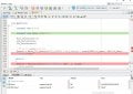
green arrow at line 306
first breakpoint set at line 314
second breakpoint set at line 318
Next I click on continue button F5
Image 2 :
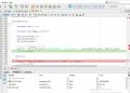
green arrow at line 314
first breakpoint set at line 314
second breakpoint set at line 318
Next I click on continue button F5
Image 3 :
green arrow at line 314
first breakpoint set at line 314
second breakpoint set at line 318
Attachments
-
 150 KB Views: 2
 -
 148.5 KB Views: 2
 -
 153.6 KB Views: 2


