PIC Development Board with PK3

Thread Starter

Djsarakar

Joined Jul 26, 2020
489
Remove the DS1307 and the ADS1115 from the circuit.
Verify that SCL and SDA are properly connected to the PIC using the continuity function on your meter
Change the slave address to 0xA0 for the EEPROM.

Delete these lines
TRISCbits.TRISC3 = 1; // Clock Pin
TRISCbits.TRISC4 = 1; // SDA Pin

and replace with:
TRISC = 0x18; in the init IO routine.

Add this line just before #include <xc.h> to disable the 'function not called' message.
#pragma warning disable 520
Done

Make sure you have a suitable capacitor on VDDCORE (pin 6). See section 2.4 in the datasheet.
as far as know VDDCORE (pin 6) is not connected to 10uF capacitor on board
I am connecting pin 6 to 10uf capacitor as shown in datasheet
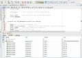
1621182591184.png1621182640132.png


Compile to NO ERRORS, NO WARNINGS. Fix any warnings. It is pointless to debug code that the compiler says has problems.
.
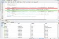
main.c:142:13: warning: implicit conversion loses integer precision: 'unsigned char' to '__bit' [-Wconversion]
ACKDT = ackflag; //specify if we should send ACK or NAK after receiving
~ ^~~~~~~

@JohnInTX I am trying to fix one warning. I looked into xc8 user manual but I don't understand how to fix this warning ?

1621182886848.png
 

Thread Starter

Djsarakar

Joined Jul 26, 2020
489
This is wiring for 4.7 K pullup resistor with three pin header and MCU SCL and DATA pins on breadboard. Not so good but its just to show you How I have done connection on breadboard

1621185204970.png
 

JohnInTX

Joined Jun 26, 2012
4,787
I am trying to fix one warning. I looked into xc8 user manual but I don't understand how to fix this warning ?
Well, you're on the right track. The basic problem is that 'ackflag', the desired value for ACK or NAK, is passed to the function as an 8 bit byte but the target value ACKDT is a single bit. (XC8 won't pass bit values as parameters). So what the warning is telling you is the compiler has applied built-in rules to determine how to set or clear ACKDT based on the value of ackflag and it wants you to know about it. In this case, the code compiles correctly but you still never want to run with warnings so you tell the compiler explicitly how to do the conversion. There are several ways to do that:
Cast the byte value to a bit:
ACKDT = (__bit) ackflag;
That tells the compiler that yes, you know how it converts bytes to bits and you're OK with it. That's OK only if you know the rules of integer promotion/demotion. It DOES work in this case because you are just confirming to the compiler that its choice was correct. And it is.

But there are other ways that might be a little better:
Assign the result of a TRUE/FALSE calculation to the single bit ACKDT:
ACKDT = (ackflag == 1);
The compiler evaluates the expression to TRUE or FALSE and assigns the result to ACKDT. That works, but depends on the values specified for ackflag being what is needed for ACKDT *AND* that those values are what the compiler uses for TRUE and FALSE representations in a byte value. Since it is the same construct you used below in ReadBlock, it's OK for your purposes but generally not a good idea.

Better: use an explicit conditional to separate the values used by ackflag from those required by ACKDT:
if (ackflag != 0)
ACKDT = 1;
else
ACKDT = 0;

Even better:
#define ACK 0
#define NAK 1

if (ackflag == NAK)
ACKDT = 1;
else
ACKDT = 0;

Then in I2C_ReceiveBlock change:
unsigned char ackflag = (buflen == 1); //1 if this is the last byte to receive => send NAK
to
unsigned char ackflag; // don't mix declaration with assigning calculated values - confusing.
...
if (buflen == 1) // 1 = last byte to receive, NAK
ackflag = NAK;
else
ackflag = ACK;


In your specific case, any of these would work. At the least, you should define the values of ackflag for ACK and NAK and use those instead of literal 1 and 0. Easier to read and you don't have to remember which is which value nor be affected by the whims of the compiler's internal representations.

The best way would be to create an enumerated type for ACK and NAK that can only have those values and use those names instead of any literal 1 or 0. That's more reliable than any of the approaches above. I'll leave it to you to investigate enumerated types in C but for now, use one of those methods described above to suppress the warning and proceed.

The wiring looks right.
How did your voltage measurements at the breakpoints work out? The idea there is to make sure that both SCL and SDA are high for an idle bus (first breakpoint) and low after Start.
 
Last edited:

Thread Starter

Djsarakar

Joined Jul 26, 2020
489
Well, you're on the right track. The basic problem is that 'ackflag', the desired value for ACK or NAK, is passed to the function as an 8 bit byte but the target value ACKDT is a single bit. (XC8 won't pass bit values as parameters).
I gone step into F7 each line of code I think debug show that slave is accepting address. This means that we shouldn't avoid compiler warnings
1621196154796.png

Edit : ignore function name ADS1115_Write. I dint write complete program. its just to test whether slave is accepting address or not accepting.
 
Last edited:

JohnInTX

Joined Jun 26, 2012
4,787
This means that we shouldn't avoid compiler warnings
Yep! The generated code looked OK but it's still a good idea to clear up any warnings.
Interesting point: compiling here for the 45K80 generated the warning but compiling for the 4685 did not, even though the generated code was identical. Whew!

Anyway, if you are getting no errors out of the ADS1115 write that's a good sign.

From here, I would do the EEPROM with the RTC and ADC removed. Change the slave address to 0xa0 and add
__delay_ms(10);
between the write and the read. Everything else should work as is.

Inspect the readbuf before and after reading. It should be 00000... before and have the RTC data after..
If that works, you can be reasonably certain that you can read and write with I2C.
Carry on!
 

Thread Starter

Djsarakar

Joined Jul 26, 2020
489
From here, I would do the EEPROM with the RTC and ADC removed. Change the slave address to 0xa0 and add
__delay_ms(10);
between the write and the read. Everything else should work as is.
Hi JohnInTX,

I don't understand what that means. I guess you want the EPROM and the RTC should be connected in the same bus. I should send an address of one and check if the slave device is accepting request or not.

Do you want two slaves on the same I2C bus?

I liked idea you gave for better program I will use enum. I will work to write better program

I appreciate your excellent effort to solve my problem
 
Last edited:

JohnInTX

Joined Jun 26, 2012
4,787
I would first just do a write to the EEPROM then read back the data, without anything else on the bus. That's what I did to debug the code.
The delay is needed because after writing to the EEPROM, it takes a few milliseconds to physically write the data inside the chip before you can read it back. It is not necessary for the RTC won't hurt to leave it in there.
The EEPROM register addressing is the same as the RTC without the questions about the battery etc. Writing the data you have to the EEPROM just writes to the first 7 locations in EE just like it would in the RTC. Once the EEPROM works, you can plug in the RTC to the socket, change the slave address and try that. Since the I2C has been verified, any problems will be part of the RTC related stuff - Vbatt etc.
Don't make any changes to the program (like trying enum) until you get first the EEPROM then the RTC working - the code is OK for now. Only work on one thing at a time. Once you have the EEPROM and RTC working then you can mess with enum and any problems that crop up then will be related to the new 'enum' since you know the I2C is working. Don't change multiple things at once, you will just be running in circles.
Yes, I2C can have many different devices on the same 2 wire bus, that is what the slave address is for - note that it is different for each of the EEPROM, RTC and ADC. That's how the chips know which one is selected. Compare with SPI which requires a separate CE/ wire for each device. I2C allows 1 to 127 separate devices on the bus to be addressed with the same 2 wires. Nice.
You're welcome. Carry on.
 

Thread Starter

Djsarakar

Joined Jul 26, 2020
489
@JohnInTX

EEPROM 24c02 hold 2KB of memory there are location from 0 to 2048.

Writing a byte of memory to the EEPROM generally happens in three steps:

  1. Send slave address 0xA0
  2. Send word register location(0 to 2048 memory location
  3. Send the data byte that store at this location (0 to 2048 memory location)

Reading from the EEPROM basically follows the two step process

  1. Send slave address 0xA1
  2. Send the Byte of the memory location that we want to read to.

I don't have idea What's happening in debugging. I want to store data in two memory location 0x00 and 0x05

C:
#define _XTAL_FREQ 20000000     // crystal 20MHz

// PIC18F45K80 Configuration Bit Settings
// CONFIG1L
#pragma config RETEN = ON       // VREG Sleep Enable bit (Ultra low-power regulator is Enabled (Controlled by SRETEN bit))
#pragma config INTOSCSEL = LOW  // LF-INTOSC Low-power Enable bit (LF-INTOSC in Low-power mode during Sleep)
// SOSCSEL = No Setting
#pragma config XINST = OFF      // Extended Instruction Set (Disabled)
// CONFIG1H
#pragma config FOSC = HS2       // HS oscillator (high power, 16 MHz-25 MHz
#pragma config PLLCFG = OFF     // PLL x4 Enable bit (Disabled)
#pragma config FCMEN = OFF      // Fail-Safe Clock Monitor (Disabled)
#pragma config IESO = OFF       // Internal External Oscillator Switch Over Mode (Disabled)
// CONFIG2L
#pragma config PWRTEN = ON      // Power Up Timer (Enabled)
#pragma config BOREN = OFF      // Brown Out Detect (Disabled in hardware, SBOREN disabled)
#pragma config BORV = 0         // Brown-out Reset Voltage bits (3.0V)
#pragma config BORPWR = LOW     // BORMV Power level (BORMV set to low power level)
// CONFIG2H
#pragma config WDTEN = OFF      // Watchdog Timer (WDT disabled in hardware; SWDTEN bit disabled)
#pragma config WDTPS = 1        // Watchdog Postscaler (1:1)
// CONFIG3H
#pragma config CANMX = PORTC    // ECAN Mux bit (ECAN TX and RX pins are located on RC6 and RC7, respectively)
#pragma config MSSPMSK = MSK5   // MSSP address masking (5 bit address masking mode)
#pragma config MCLRE = ON      // Master Clear Enable (MCLR Enabled, RE3 Disabled)
// CONFIG4L
#pragma config STVREN = OFF     // Stack Overflow Reset (Disabled)
#pragma config BBSIZ = BB1K     // Boot Block Size (1K word Boot Block size)
// CONFIG5L
#pragma config CP0 = ON         // Code Protect 00800-01FFF (Enabled)
#pragma config CP1 = ON         // Code Protect 02000-03FFF (Enabled)
#pragma config CP2 = ON         // Code Protect 04000-05FFF (Enabled)
#pragma config CP3 = ON         // Code Protect 06000-07FFF (Enabled)
// CONFIG5H
#pragma config CPB = ON         // Code Protect Boot (Enabled)
#pragma config CPD = ON         // Data EE Read Protect (Enabled)
// CONFIG6L
#pragma config WRT0 = ON        // Table Write Protect 00800-01FFF (Enabled)
#pragma config WRT1 = ON        // Table Write Protect 02000-03FFF (Enabled)
#pragma config WRT2 = ON        // Table Write Protect 04000-05FFF (Enabled)
#pragma config WRT3 = ON        // Table Write Protect 06000-07FFF (Enabled)
// CONFIG6H
#pragma config WRTC = ON        // Config. Write Protect (Enabled)
#pragma config WRTB = ON        // Table Write Protect Boot (Enabled)
#pragma config WRTD = ON        // Data EE Write Protect (Enabled)
// CONFIG7L
#pragma config EBTR0 = ON       // Table Read Protect 00800-01FFF (Enabled)
#pragma config EBTR1 = ON       // Table Read Protect 02000-03FFF (Enabled)
#pragma config EBTR2 = ON       // Table Read Protect 04000-05FFF (Enabled)
#pragma config EBTR3 = ON       // Table Read Protect 06000-07FFF (Enabled)
// CONFIG7H
#pragma config EBTRB = ON       // Table Read Protect Boot (Enabled)
// #pragma config statements should precede project file includes.
// Use project enums instead of #define for ON and OFF.

#pragma warning disable 520

#include <xc.h>

#define EEPROM_ADDRESS_Write 0xA0    //I2C slave address of 24c02 (8 bit format)
#define EEPROM_ADDRESS_Read 0xA1    //I2C slave address of 24c02 (8 bit format)

#define Word_Address1  0x01
#define Word_Address2  0x05


unsigned char Result1;
unsigned char Result2;
unsigned char Result3;
unsigned char Result4;


void Port_Initialized (void)
{

// LATx registers
    LATA =  0x00;
    LATB =  0x00;
    LATC =  0x00;
    LATD =  0x00;
    LATE =  0x00;

//  TRISx registers
    TRISA = 0x00;    // All are output, Unused
    TRISB = 0x00;   // all are output, Unused
    TRISC = 0x18;    //
    TRISD = 0x00;   // all are output, Unused
    TRISE = 0x00;   // All are output, Unused
  
    ANCON0 = 0x00;    // digital
    ANCON1 = 0x00;    // Set to digital port
    CM1CON = 0x00;      // Comparator off
    CM2CON = 0x00;      // Comparator off
    ADCON0 = 0x00;      // A/D conversion Disabled
    ADCON1 = 0x00;      // A/D conversion Disabled
    ADCON2 = 0x00;     // A/D conversion Disabled
}

//Initialize I2C in master mode
void I2C_Initialized(void)
{
    SSPSTAT=0x80; //Slew rate control is disabled for Standard Speed mode (100 kHz and 1 MHz)
    SSPCON1=0x28; // I2C Master mode, clock = FOSC/(4 * (SSPADD + 1))
    SSPCON2=0x00;
    SSPADD = 49;  //100kHz clock @ 20MHz Fosc SSPADD = ( (Fosc/4) / BiteRate )-1   
   // SSPADD = ( 20MHz / 100KHz ) - 1 = 49 //
}

// Send an I2C START
// Return 0 if all ok, 1 if bus collision
__bit I2C_Start(void)
{
    BCLIF = 0;  //Clear 'Bus collision" flag
    SEN = 1;    //initiate a START cycle
    while (SEN);    //wait until it has been sent
    return BCLIF;   //return value of BCLIF flag
}
// Send an I2C STOP
void I2C_Stop(void)
{
    PEN = 1;    //initiate a STOP cycle
    while (PEN);    //wait until it has been sent
}
// Send an I2C REPEATED START
void I2C_Restart(void)
{
    RSEN = 1;    //initiate a REPEATED START cycle
    while (RSEN);    //wait until it has been sent
}
//Receive one byte. ackflag=0 to send ACK, or 1 to send NAK in reply
//Send one byte. Return 0 if ACK received, or 1 if NAK received
__bit I2C_Sendbyte(unsigned char dat)
{
    SSPBUF = dat;

    asm("nop");     // <<<--- wait a little for R_W to be set

    while (R_W);    //wait until byte sent and ACK/NAK received
    return ACKSTAT;
}

unsigned char I2C_Recvbyte(unsigned char ackflag)
{
    RCEN = 1;   // initiate a RECEIVE cycle
    ACKDT =(__bit)ackflag;    //specify if we should send ACK or NAK after receiving
    while (RCEN);   //wait until RECEIVE has completed
    ACKEN = 1;  //initiate an ACK cycle
    while (ACKEN);  //wait until it has completed
    return SSPBUF;
}
//Send an array of data to an I2C device.
//Return 0 if all OK, 1 if bus error, 2 if slave address NAK, 3 if slave register NAK, 4 if slave data NAK
unsigned char EEPROM_Write(unsigned char slave_address, unsigned char start_reg, unsigned char buflen, const unsigned char * bufptr)
{
    if (I2C_Start() )   //send a start, and check if it succeeded
        return 1;   //abort if bus collision
    //send the I2C slave address (force R/W bit low)
    if (I2C_Sendbyte(slave_address))
    {
        I2C_Stop(); //if address was NAKed, terminate the cycle
        return 2;   //and return error code
    }
    //send the device register index
    if (I2C_Sendbyte(start_reg))
    {
        I2C_Stop(); //if register was NAKed, terminate the cycle
        return 3;   //and return error code
    }
    //send the data. buflen might be zero!
    for (; buflen>0; --buflen)
    {
        if (I2C_Sendbyte(*bufptr++))
        {
            I2C_Stop(); //if register was NAKed, terminate the cycle
            return 4;   //and return error code
        }
  
    }
    I2C_Stop();
    return 0;   //no error
}
//Receive an array of data from an I2C device.
//Return 0 if all OK, 1 if bus error, 2 if slave address NAK, 3 if slave register NAK
unsigned char EEPROM_Read(unsigned char slave_address, unsigned char start_reg, unsigned char buflen, unsigned char * bufptr)
{
    //do a dummy zero length write cycle to set the register address
    unsigned char retval = EEPROM_Write(slave_address, start_reg, 0, 0);
    if (retval)
    {
        return retval;  //abort if there was an error
    }
    //now start the READ cycle
    if (I2C_Start() )   //send a start, and check if it succeeded
        return 1;   //abort if bus collision
    //send the I2C slave address (force the R/W bit high)
    if (I2C_Sendbyte(slave_address | 0x01))
    {
        I2C_Stop(); //if address was NAKed, terminate the cycle
        return 2;   //and return error code
    }
    //receive the data.
    for (; buflen>0; --buflen)
    {
        unsigned char ackflag = (buflen == 1);   //1 if this is the last byte to receive => send NAK
      
        *bufptr++ = I2C_Recvbyte(ackflag);
    }
    I2C_Stop();
    return 0;   //no error
}
const unsigned char EEPROM_data[] =
{
    0x07,   // Count 7
    0x06,   // Count 6
    0x05,   // Count 5
    0x04,   // Count 4
    0x03,   // Count 3
    0x02,   // Count 2
    0x01,   // Count 1
};
unsigned char rd_buf[7];

void main(void)
{
     Port_Initialized ();
     I2C_Initialized();

    Result1 = EEPROM_Write(EEPROM_ADDRESS_Write , Word_Address1 , sizeof(EEPROM_data), EEPROM_data);
    __delay_ms(10);
    Result2 = (EEPROM_Read(EEPROM_ADDRESS_Read, Word_Address1 , sizeof(rd_buf), rd_buf) );
     __delay_ms(10);
    Result3 = EEPROM_Write(EEPROM_ADDRESS_Write , Word_Address2 , sizeof(EEPROM_data), EEPROM_data);
     __delay_ms(10);
    Result4 = (EEPROM_Read(EEPROM_ADDRESS_Read, Word_Address2 , sizeof(rd_buf), rd_buf) );
    __delay_ms(10);
    while(1);   //endless loop to avoid exiting main() function)
}
 

Attachments

Last edited:

JohnInTX

Joined Jun 26, 2012
4,787
Clarifications in the quotes are in bold
EEPROM 24c02 hold 2KB of memory there are location from 0 to 2048.
My schematic shows a 24C04 but if you have a 24C02 that's fine too. The 24C02 is a 2K BIT (not byte) EEPROM organized as 256 x 8.

Writing a byte of memory to the EEPROM generally happens in three steps:
  1. Send slave address 0xA0
  2. Send word register location(0 to 255 memory address)
  3. Send the data byte that store at this location (0 to 255 memory address)
4. Send STOP to complete the transaction.

Reading from the EEPROM basically follows the two step process
  1. Send slave address 0xA1
  2. Send the address of the memory location that we want to read from.
Re 2: how do you send the address of the memory location to read from when you are reading? Answer: look at line 187 in I2C ReadBlock. For any read, you must first WRITE the address that you want to read from using an I2C write operation THEN do another I2C operation to read from that previously set address. The WRITE and READ operations are separated by a REPEAT START and the whole operation is ended with a STOP. See FIGURE 9-2 RANDOM READ in the attached datasheet. Then study the transactions for the other operations. Its for a 24C04 but the operation is the same for a 24C02.

This method for reading is typical of all I2C devices including your 1307 RTC. To read, you must first set the internal address pointer using a WRITE then do a REPEAT START, SLAVE ADDRESS + READ then read N bytes. Each byte read increments the internal address pointer. The master ACKs each byte read except for the last one where it sends a NAK to stop reading and STOP to end the operation and free the bus.

Once you understand all of that, look at ReadBlock and WriteBlock. Both have what is needed to do almost all of that but you are not calling them correctly. Review the descriptions for each and figure out how to call those routines for different numbers of bytes to read/write. After that, we can add a few things to make them work for ANY I2C device, not just the EE or RTC.

Carry on
 

Attachments

Thread Starter

Djsarakar

Joined Jul 26, 2020
489
Once you understand all of that, look at ReadBlock and WriteBlock. Both have what is needed to do almost all of that but you are not calling them correctly. Review the descriptions for each and figure out how to call those routines for different numbers of bytes to read/write. After that, we can add a few things to make them work for ANY I2C device, not just the EE or RTC.
Carry on
This observation show PIC sending seven bytes to internal register's of EEPROM

1621434711017.png

The only problem with multiple read function. I have already sent seven bytes to internal register address and now I want to read data store at internal register address of eeprom

What's the problem in read function Why I am getting NULL value while I have been sent data ?

1621434969712.png
 

Thread Starter

Djsarakar

Joined Jul 26, 2020
489
Post the current code?

In line #193 above it should be sending a Repeat Start instead of a Start.
Current code with debug screenshot

C:
#define _XTAL_FREQ 20000000     // crystal 20MHz

// PIC18F45K80 Configuration Bit Settings
// CONFIG1L
#pragma config RETEN = ON       // VREG Sleep Enable bit (Ultra low-power regulator is Enabled (Controlled by SRETEN bit))
#pragma config INTOSCSEL = LOW  // LF-INTOSC Low-power Enable bit (LF-INTOSC in Low-power mode during Sleep)
// SOSCSEL = No Setting
#pragma config XINST = OFF      // Extended Instruction Set (Disabled)
// CONFIG1H
#pragma config FOSC = HS2       // HS oscillator (high power, 16 MHz-25 MHz
#pragma config PLLCFG = OFF     // PLL x4 Enable bit (Disabled)
#pragma config FCMEN = OFF      // Fail-Safe Clock Monitor (Disabled)
#pragma config IESO = OFF       // Internal External Oscillator Switch Over Mode (Disabled)
// CONFIG2L
#pragma config PWRTEN = ON      // Power Up Timer (Enabled)
#pragma config BOREN = OFF      // Brown Out Detect (Disabled in hardware, SBOREN disabled)
#pragma config BORV = 0         // Brown-out Reset Voltage bits (3.0V)
#pragma config BORPWR = LOW     // BORMV Power level (BORMV set to low power level)
// CONFIG2H
#pragma config WDTEN = OFF      // Watchdog Timer (WDT disabled in hardware; SWDTEN bit disabled)
#pragma config WDTPS = 1        // Watchdog Postscaler (1:1)
// CONFIG3H
#pragma config CANMX = PORTC    // ECAN Mux bit (ECAN TX and RX pins are located on RC6 and RC7, respectively)
#pragma config MSSPMSK = MSK5   // MSSP address masking (5 bit address masking mode)
#pragma config MCLRE = ON      // Master Clear Enable (MCLR Enabled, RE3 Disabled)
// CONFIG4L
#pragma config STVREN = OFF     // Stack Overflow Reset (Disabled)
#pragma config BBSIZ = BB1K     // Boot Block Size (1K word Boot Block size)
// CONFIG5L
#pragma config CP0 = ON         // Code Protect 00800-01FFF (Enabled)
#pragma config CP1 = ON         // Code Protect 02000-03FFF (Enabled)
#pragma config CP2 = ON         // Code Protect 04000-05FFF (Enabled)
#pragma config CP3 = ON         // Code Protect 06000-07FFF (Enabled)
// CONFIG5H
#pragma config CPB = ON         // Code Protect Boot (Enabled)
#pragma config CPD = ON         // Data EE Read Protect (Enabled)
// CONFIG6L
#pragma config WRT0 = ON        // Table Write Protect 00800-01FFF (Enabled)
#pragma config WRT1 = ON        // Table Write Protect 02000-03FFF (Enabled)
#pragma config WRT2 = ON        // Table Write Protect 04000-05FFF (Enabled)
#pragma config WRT3 = ON        // Table Write Protect 06000-07FFF (Enabled)
// CONFIG6H
#pragma config WRTC = ON        // Config. Write Protect (Enabled)
#pragma config WRTB = ON        // Table Write Protect Boot (Enabled)
#pragma config WRTD = ON        // Data EE Write Protect (Enabled)
// CONFIG7L
#pragma config EBTR0 = ON       // Table Read Protect 00800-01FFF (Enabled)
#pragma config EBTR1 = ON       // Table Read Protect 02000-03FFF (Enabled)
#pragma config EBTR2 = ON       // Table Read Protect 04000-05FFF (Enabled)
#pragma config EBTR3 = ON       // Table Read Protect 06000-07FFF (Enabled)
// CONFIG7H
#pragma config EBTRB = ON       // Table Read Protect Boot (Enabled)
// #pragma config statements should precede project file includes.
// Use project enums instead of #define for ON and OFF.

#pragma warning disable 520

#include <xc.h>

#define EEPROM_ADDRESS_Write 0xA0    //I2C slave address of 24c02 (8 bit format)
#define EEPROM_ADDRESS_Read 0xA1    //I2C slave address of 24c02 (8 bit format)

#define Word_Address1  0x05
#define Word_Address2  0x05


unsigned char Result1;
unsigned char Result2;
unsigned char Result3;
unsigned char Result4;


void Port_Initialized (void)
{

// LATx registers
    LATA =  0x00;
    LATB =  0x00;
    LATC =  0x00;
    LATD =  0x00;
    LATE =  0x00;

//  TRISx registers
    TRISA = 0x00;    // All are output, Unused
    TRISB = 0x00;   // all are output, Unused
    TRISC = 0x18;    //
    TRISD = 0x00;   // all are output, Unused
    TRISE = 0x00;   // All are output, Unused
 
    ANCON0 = 0x00;    // digital
    ANCON1 = 0x00;    // Set to digital port
    CM1CON = 0x00;      // Comparator off
    CM2CON = 0x00;      // Comparator off
    ADCON0 = 0x00;      // A/D conversion Disabled
    ADCON1 = 0x00;      // A/D conversion Disabled
    ADCON2 = 0x00;     // A/D conversion Disabled
}

//Initialize I2C in master mode
void I2C_Initialized(void)
{
    SSPSTAT=0x80; //Slew rate control is disabled for Standard Speed mode (100 kHz and 1 MHz)
    SSPCON1=0x28; // I2C Master mode, clock = FOSC/(4 * (SSPADD + 1))
    SSPCON2=0x00;
    SSPADD = 49;  //100kHz clock @ 20MHz Fosc SSPADD = ( (Fosc/4) / BiteRate )-1   
   // SSPADD = ( 20MHz / 100KHz ) - 1 = 49 //
}

// Send an I2C START
// Return 0 if all ok, 1 if bus collision
__bit I2C_Start(void)
{
    BCLIF = 0;  //Clear 'Bus collision" flag
    SEN = 1;    //initiate a START cycle
    while (SEN);    //wait until it has been sent
    return BCLIF;   //return value of BCLIF flag
}
// Send an I2C STOP
void I2C_Stop(void)
{
    PEN = 1;    //initiate a STOP cycle
    while (PEN);    //wait until it has been sent
}
// Send an I2C REPEATED START
void I2C_Restart(void)
{
    RSEN = 1;    //initiate a REPEATED START cycle
    while (RSEN);    //wait until it has been sent
}
//Receive one byte. ackflag=0 to send ACK, or 1 to send NAK in reply
//Send one byte. Return 0 if ACK received, or 1 if NAK received
__bit I2C_Sendbyte(unsigned char dat)
{
    SSPBUF = dat;

    asm("nop");     // <<<--- wait a little for R_W to be set

    while (R_W);    //wait until byte sent and ACK/NAK received
    return ACKSTAT;
}

unsigned char I2C_Recvbyte(unsigned char ackflag)
{
    RCEN = 1;   // initiate a RECEIVE cycle
    ACKDT =(__bit)ackflag;    //specify if we should send ACK or NAK after receiving
    while (RCEN);   //wait until RECEIVE has completed
    ACKEN = 1;  //initiate an ACK cycle
    while (ACKEN);  //wait until it has completed
    return SSPBUF;
}
//Send an array of data to an I2C device.
//Return 0 if all OK, 1 if bus error, 2 if slave address NAK, 3 if slave register NAK, 4 if slave data NAK
unsigned char EEPROM_Write(unsigned char slave_address, unsigned char start_reg, unsigned char buflen, const unsigned char * bufptr)
{
    if (I2C_Start() )   //send a start, and check if it succeeded
        return 1;   //abort if bus collision
    //send the I2C slave address (force R/W bit low)
    if (I2C_Sendbyte(slave_address))
    {
        I2C_Stop(); //if address was NAKed, terminate the cycle
        return 2;   //and return error code
    }
    //send the device register index
    if (I2C_Sendbyte(start_reg))
    {
        I2C_Stop(); //if register was NAKed, terminate the cycle
        return 3;   //and return error code
    }
    //send the data. buflen might be zero!
    for (; buflen>0; --buflen)
    {
        if (I2C_Sendbyte(*bufptr++))
        {
            I2C_Stop(); //if register was NAKed, terminate the cycle
            return 4;   //and return error code
        }
 
    }
    I2C_Stop();
    return 0;   //no error
}
//Receive an array of data from an I2C device.
//Return 0 if all OK, 1 if bus error, 2 if slave address NAK, 3 if slave register NAK
unsigned char EEPROM_Read(unsigned char slave_address, unsigned char start_reg, unsigned char buflen, unsigned char * bufptr)
{
    //do a dummy zero length write cycle to set the register address
    unsigned char retval = EEPROM_Write(slave_address, start_reg, 0, 0);
    if (retval)
    {
        return retval;  //abort if there was an error
    }
    //now start the READ cycle
    if (I2C_Start() )   //send a start, and check if it succeeded
        return 1;   //abort if bus collision
    //send the I2C slave address (force the R/W bit high)
    if (I2C_Sendbyte(slave_address | 0x01))
    {
        I2C_Stop(); //if address was NAKed, terminate the cycle
        return 2;   //and return error code
    }
    //receive the data.
    for (; buflen>0; --buflen)
    {
        unsigned char ackflag = (buflen == 1);   //1 if this is the last byte to receive => send NAK
      
        *bufptr++ = I2C_Recvbyte(ackflag);
    }
    I2C_Stop();
    return 0;   //no error
}
const unsigned char EEPROM_data[] =
{
    0x07,   // Count 7
    0x06,   // Count 6
    0x05,   // Count 5
    0x04,   // Count 4
    0x03,   // Count 3
    0x02,   // Count 2
    0x01,   // Count 1
};
unsigned char rd_buf[7];

void main(void)
{
     Port_Initialized ();
     I2C_Initialized();

    Result1 = EEPROM_Write(EEPROM_ADDRESS_Write , Word_Address1 , sizeof(EEPROM_data), EEPROM_data);
    __delay_ms(10);
    Result2 = (EEPROM_Read(EEPROM_ADDRESS_Read, Word_Address1 , sizeof(rd_buf), rd_buf) );
     __delay_ms(10);
    Result3 = EEPROM_Write(EEPROM_ADDRESS_Write , Word_Address2 , sizeof(EEPROM_data), EEPROM_data);
     __delay_ms(10);
    Result4 = (EEPROM_Read(EEPROM_ADDRESS_Read, Word_Address2 , sizeof(rd_buf), rd_buf) );
    __delay_ms(10);
    while(1);   //endless loop to avoid exiting main() function)
}
Read.jpg
 

Attachments

JohnInTX

Joined Jun 26, 2012
4,787
You correctly specified the complete EEPROM slave address including the R/W- bit BUT the code expected only the base address but had a bug there too. In line 73, the comment says that the R/W bit is forced to the correct value by what the code is doing but it was not doing it. That caused a problem in 'Read' when it tried to write the register address. I prefer to specify the slave address and let the code fix up the R/W- bit.

The rest was OK but you are not paying attention to the paged nature of the EEPROM. Review the datasheet. The EE is broken into 8 byte rows - 00-07, 08 - 0F etc. You can only write up to 8 bytes in one operation and you can't cross a row boundary in one operation. For example you can write 4 bytes from 01h-04h but you can't write 4 bytes from 06h-09h because that crosses the row boundary at 08h. Bigger EEPROMs have bigger write buffers but all have some similar limitations. Read the PAGE PROGRAM MODE section in the datasheet.

I edited the code to show how to write one byte. Note how the number of bytes to read or write is specified in the single byte operation.

The capture of the EE operations is attached.
The first write is shown in Index 1.
The first read is shown at Index 2 and 3. Note that to read, you must first WRITE the EE byte address then READ from that address in a new I2C transaction.
The second write is at Index 4
The second read is at Index 5 and 6.

SP means that the message has a Start and stoP.
* means NAK, Note how the last byte read in the READ operations is NAKed.
ADDR is the slave address shifted right one bit - A0h >> 1 = 50h. It's just how they display it.

Note that the code is just the I2C stuff. I have the IO and CONFIG off in other files because I am switching between chips. You'll have to copy this into your code at the appropriate place.

Have fun!


C:
//
       // <<---- The code should set the R/W bit according to its function
#define EEPROM_ADDRESS 0xA0         //I2C slave address of 24c02 (8 bit format)
//#define EEPROM_ADDRESS_Read 0xA1    // let the code do this

#define Word_Address1  0x00  // <<<--- Original address violated EE row boundary

unsigned char Result1;
unsigned char Result2;
unsigned char Result3;
unsigned char Result4;


//Initialize I2C in master mode
void I2C_Initialized(void)
{
    SSPSTAT=0x80; //Slew rate control is disabled for Standard Speed mode (100 kHz and 1 MHz)
    SSPCON1=0x28; // I2C Master mode, clock = FOSC/(4 * (SSPADD + 1))
    SSPCON2=0x00;
    SSPADD = 49;  //100kHz clock @ 20MHz Fosc SSPADD = ( (Fosc/4) / BiteRate )-1
   // SSPADD = ( 20MHz / 100KHz ) - 1 = 49 //
}

// Send an I2C START
// Return 0 if all ok, 1 if bus collision
__bit I2C_Start(void)
{
    BCLIF = 0;  //Clear 'Bus collision" flag
    SEN = 1;    //initiate a START cycle
    while (SEN);    //wait until it has been sent
    return BCLIF;   //return value of BCLIF flag
}
// Send an I2C STOP
void I2C_Stop(void)
{
    PEN = 1;    //initiate a STOP cycle
    while (PEN);    //wait until it has been sent
}
// Send an I2C REPEATED START
void I2C_Restart(void)
{
    RSEN = 1;    //initiate a REPEATED START cycle
    while (RSEN);    //wait until it has been sent
}
//Receive one byte. ackflag=0 to send ACK, or 1 to send NAK in reply
//Send one byte. Return 0 if ACK received, or 1 if NAK received
__bit I2C_Sendbyte(unsigned char dat)
{
    SSPBUF = dat;

    asm("nop");     // <<<--- wait a little for R_W to be set

    while (R_W);    //wait until byte sent and ACK/NAK received
    return ACKSTAT;
}

unsigned char I2C_Recvbyte(unsigned char ackflag)
{
    RCEN = 1;   // initiate a RECEIVE cycle
    ACKDT =(__bit)ackflag;    //specify if we should send ACK or NAK after receiving
    while (RCEN);   //wait until RECEIVE has completed
    ACKEN = 1;  //initiate an ACK cycle
    while (ACKEN);  //wait until it has completed
    return SSPBUF;
}
//Send an array of data to an I2C device.
//Return 0 if all OK, 1 if bus error, 2 if slave address NAK, 3 if slave register NAK, 4 if slave data NAK
unsigned char EEPROM_Write(unsigned char slave_address, unsigned char start_reg, unsigned char buflen, const unsigned char * bufptr)
{
    if (I2C_Start() )   //send a start, and check if it succeeded
        return 1;   //abort if bus collision
    //send the I2C slave address (force R/W bit low)
    if (I2C_Sendbyte(slave_address & 0xfe))  // <<---- Added AND to force R/W- low.  Comment said it but code didn't do it
    {
        I2C_Stop(); //if address was NAKed, terminate the cycle
        return 2;   //and return error code
    }
    //send the device register index
    if (I2C_Sendbyte(start_reg))
    {
        I2C_Stop(); //if register was NAKed, terminate the cycle
        return 3;   //and return error code
    }
    //send the data. buflen might be zero!
    for (; buflen>0; --buflen)
    {
        if (I2C_Sendbyte(*bufptr++))
        {
            I2C_Stop(); //if register was NAKed, terminate the cycle
            return 4;   //and return error code
        }

    }
    I2C_Stop();
    return 0;   //no error
}
//Receive an array of data from an I2C device.
//Return 0 if all OK, 1 if bus error, 2 if slave address NAK, 3 if slave register NAK
unsigned char EEPROM_Read(unsigned char slave_address, unsigned char start_reg, unsigned char buflen, unsigned char * bufptr)
{
    //do a dummy zero length write cycle to set the register address
    unsigned char retval = EEPROM_Write(slave_address, start_reg, 0, 0);
    if (retval)
    {
        return retval;  //abort if there was an error
    }
    //now start the READ cycle
    if (I2C_Start() )   //send a start, and check if it succeeded
        return 1;   //abort if bus collision
    //send the I2C slave address (force the R/W bit high)
    if (I2C_Sendbyte(slave_address | 0x01))
    {
        I2C_Stop(); //if address was NAKed, terminate the cycle
        return 2;   //and return error code
    }
    //receive the data.
    for (; buflen>0; --buflen)
    {
        unsigned char ackflag = (buflen == 1);   //1 if this is the last byte to receive => send NAK

        *bufptr++ = I2C_Recvbyte(ackflag);
    }
    I2C_Stop();
    return 0;   //no error
}
const unsigned char EEPROM_data[] =
{
    0x07,   // Count 7
    0x06,   // Count 6
    0x05,   // Count 5
    0x04,   // Count 4
    0x03,   // Count 3
    0x02,   // Count 2
    0x01,   // Count 1
};
unsigned char rd_buf[7];

// Test variable for one byte transfer
const unsigned char testchar = 'A';
unsigned char testchar_readback = 0xff;  // init to this to see difference after read

void main(void)
{
     Port_Initialized ();
     I2C_Initialized();

        // Write test buffer
    Result1 = EEPROM_Write(EEPROM_ADDRESS , Word_Address1 , sizeof(EEPROM_data), EEPROM_data);
    __delay_ms(10);
        // Read test buffer back
    Result2 = EEPROM_Read(EEPROM_ADDRESS, Word_Address1 , sizeof(rd_buf), rd_buf) ;
     __delay_ms(10);
        // Write ONE character to location 0x15
    Result3 = EEPROM_Write(EEPROM_ADDRESS, 0x15 , 1, &testchar);
     __delay_ms(10);
        // Read back ONE character from 0x15
    Result4 = EEPROM_Read(EEPROM_ADDRESS, 0x15 , 1, &testchar_readback);
    __delay_ms(10);
    while(1);   //endless loop to avoid exiting main() function)
}
 

Attachments

Last edited:

hexreader

Joined Apr 16, 2011
619
SPOILER ALERT ......

I have working code, written with MPLABX and XC8.
Provides handy diagnostic program for I2C EEPROM and 1307 RTC.
PIC18F45K80 with 20MHz 2-pin Crystal - needs serial port connection and PC Terminal program

Will only post if DJ wants me to. Don't want to ruin the learning experience of doing it yourself.

Code is terrible and not a good example to learn from, but it might serve to test whether the hardware works.
It troubled me that I was able to write mikroC code for EEPROM and 1307, but not experienced enough to do it with MPLAB and XC8. It took many hours to get something working with XC8 and I am very unhappy with the quality of the result, but the project does seem to work. The code is cobbled together from DJ's UART code, my mikroC code and John's fixes.

I lay no claim to the code (and would not want to admit to writing something so terrible) - so you (DJ) are free to use, ignore, delete or improve.

Let me know if you want me to post the hex and/or XC8 source code
 

Thread Starter

Djsarakar

Joined Jul 26, 2020
489
I have working code, written with MPLABX and XC8. Will only post if DJ wants me to. Don't want to ruin the learning experience of doing it yourself.

Let me know if you want me to post the hex and/or XC8 source code
@hexreader yes of course I would like to see your code but not now. sorry please don't mind. I want to try my own first

@JohnInTX I am sorry for terrible indenting code. Main goal is to write program for real time clock but we are working with EEPROM. I want to display the data that is stored at EPPROM device. I have added display code.

1621516472070.png


C:
//
#define _XTAL_FREQ 20000000     // crystal 20MHz

// PIC18F45K80 Configuration Bit Settings
// CONFIG1L
#pragma config RETEN = ON       // VREG Sleep Enable bit (Ultra low-power regulator is Enabled (Controlled by SRETEN bit))
#pragma config INTOSCSEL = LOW  // LF-INTOSC Low-power Enable bit (LF-INTOSC in Low-power mode during Sleep)
// SOSCSEL = No Setting
#pragma config XINST = OFF      // Extended Instruction Set (Disabled)
// CONFIG1H
#pragma config FOSC = HS2       // HS oscillator (high power, 16 MHz-25 MHz
#pragma config PLLCFG = OFF     // PLL x4 Enable bit (Disabled)
#pragma config FCMEN = OFF      // Fail-Safe Clock Monitor (Disabled)
#pragma config IESO = OFF       // Internal External Oscillator Switch Over Mode (Disabled)
// CONFIG2L
#pragma config PWRTEN = ON      // Power Up Timer (Enabled)
#pragma config BOREN = OFF      // Brown Out Detect (Disabled in hardware, SBOREN disabled)
#pragma config BORV = 0         // Brown-out Reset Voltage bits (3.0V)
#pragma config BORPWR = LOW     // BORMV Power level (BORMV set to low power level)
// CONFIG2H
#pragma config WDTEN = OFF      // Watchdog Timer (WDT disabled in hardware; SWDTEN bit disabled)
#pragma config WDTPS = 1        // Watchdog Postscaler (1:1)
// CONFIG3H
#pragma config CANMX = PORTC    // ECAN Mux bit (ECAN TX and RX pins are located on RC6 and RC7, respectively)
#pragma config MSSPMSK = MSK5   // MSSP address masking (5 bit address masking mode)
#pragma config MCLRE = ON      // Master Clear Enable (MCLR Enabled, RE3 Disabled)
// CONFIG4L
#pragma config STVREN = OFF     // Stack Overflow Reset (Disabled)
#pragma config BBSIZ = BB1K     // Boot Block Size (1K word Boot Block size)
// CONFIG5L
#pragma config CP0 = ON         // Code Protect 00800-01FFF (Enabled)
#pragma config CP1 = ON         // Code Protect 02000-03FFF (Enabled)
#pragma config CP2 = ON         // Code Protect 04000-05FFF (Enabled)
#pragma config CP3 = ON         // Code Protect 06000-07FFF (Enabled)
// CONFIG5H
#pragma config CPB = ON         // Code Protect Boot (Enabled)
#pragma config CPD = ON         // Data EE Read Protect (Enabled)
// CONFIG6L
#pragma config WRT0 = ON        // Table Write Protect 00800-01FFF (Enabled)
#pragma config WRT1 = ON        // Table Write Protect 02000-03FFF (Enabled)
#pragma config WRT2 = ON        // Table Write Protect 04000-05FFF (Enabled)
#pragma config WRT3 = ON        // Table Write Protect 06000-07FFF (Enabled)
// CONFIG6H
#pragma config WRTC = ON        // Config. Write Protect (Enabled)
#pragma config WRTB = ON        // Table Write Protect Boot (Enabled)
#pragma config WRTD = ON        // Data EE Write Protect (Enabled)
// CONFIG7L
#pragma config EBTR0 = ON       // Table Read Protect 00800-01FFF (Enabled)
#pragma config EBTR1 = ON       // Table Read Protect 02000-03FFF (Enabled)
#pragma config EBTR2 = ON       // Table Read Protect 04000-05FFF (Enabled)
#pragma config EBTR3 = ON       // Table Read Protect 06000-07FFF (Enabled)
// CONFIG7H
#pragma config EBTRB = ON       // Table Read Protect Boot (Enabled)
// #pragma config statements should precede project file includes.
// Use project enums instead of #define for ON and OFF.

#pragma warning disable 520

#include <xc.h>

unsigned char Result1;
unsigned char Result2;
unsigned char Result3;
unsigned char Result4;

// The code should set the R/W bit according to its function
#define EEPROM_ADDRESS      0xA0         //I2C slave address of 24c02 (8 bit format)
#define Word_Address1       0x00


#define LCD_RS              LATBbits.LATB4
#define LCD_TRIS_RS         TRISBbits.TRISB4
#define LCD_RW              LATBbits.LATB5
#define LCD_TRIS_RW         TRISBbits.TRISB5
#define LCD_E               LATBbits.LATB6
#define LCD_TRIS_E          TRISBbits.TRISB6

#define  LCDPORT            LATD
#define  LCDTRISD           LATD

void Port_Initialized (void);
void WriteNibble(unsigned char command);
void WaitLCDBusy(void);
void WriteCommand(unsigned char command);

void Port_Initialized (void)
{
// LATx registers
    LATA =  0x00;
    LATB =  0x00;
    LATC =  0x00;
    LATD =  0x00;
    LATE =  0x00;

//  TRISx registers
    TRISA = 0x00;    // All are output, Unused
    TRISB = 0x00; 
    TRISC = 0x18;  
    TRISD = 0x00; 
    TRISE = 0x00;   // All are output, Unused

    ANCON0 = 0x00;    // digital port
    ANCON1 = 0x00;    // Set to digital port
    CM1CON = 0x00;      // Comparator off
    CM2CON = 0x00;      // Comparator off
    ADCON0 = 0x00;      // A/D conversion Disabled
    ADCON1 = 0x00;      // A/D conversion Disabled
    ADCON2 = 0x00;     // A/D conversion Disabled
}

void WaitLCDBusy(void)
{
    __delay_ms(5);
}

//Send a command to the LCD
void WriteCommand(unsigned char command)
{
    WaitLCDBusy();                        //wait until not busy
    LCD_RS = 0;                           //setup to send command
    WriteNibble(command);                 //write the high nibble
    WriteNibble( (unsigned char)(command<<4) ); //then the low nibble
}

//Initialized  LCD
void LCD_Initialized()
{
    LCDTRISD &=0x0f;                //ensure data bits are output
    LCD_E=0;                        //clear enable
    LCD_RS = 0;                     //going to write command
    LCD_TRIS_E=0;                   //Set enable to output
    LCD_TRIS_RS=0;                  //set RS to output
    LCD_TRIS_RW=0;
    LCD_RW=0;
    __delay_ms(30);                 //delay for LCD to initialise.
    WriteNibble(0x30);              //Required for initialisation
    __delay_ms(5);                  //required delay
    WriteNibble(0x30);              //Required for initialisation
    __delay_ms(1);                  //required delay
    WriteCommand(0x20);             //set to 4 bit interface
    WriteCommand(0x2c);             //set to 4 bit interface, 2 line and 5*10 font
    WriteCommand(0x01);             //clear display
    WriteCommand(0x06);             //move cursor right after write
    WriteCommand(0x0C);             //turn on display
}

//Send a character to the LCD
void WriteChar(unsigned char chr)
{
    WaitLCDBusy();                         //wait until not busy
    LCD_RS=1;                              //Setup to send character
    WriteNibble(chr);                      //write the high nibble        
    WriteNibble( (unsigned char)(chr<<4)); //then the low nibble
}

//Send any 4 bits to the LCD
void WriteNibble(unsigned char command)
{
    LCDPORT &= 0x0f;                        //clear the data bits
    LCDPORT|=((command & 0xf0));            //or in the new data
    LCD_E = 1;                              //enable the LCD interface
    NOP();                                  //change to delay of 1uS
    NOP();
    NOP();
    LCD_E = 0;                              //disable it
}

void LCD_Data( unsigned char *string)
{
    while (*string != '\0')
    {
      WriteChar(*string);
        string++;
    }
}

//Initialize I2C in master mode
void I2C_Initialized(void)
{
    SSPSTAT=0x80; //Slew rate control is disabled for Standard Speed mode (100 kHz and 1 MHz)
    SSPCON1=0x28; // I2C Master mode, clock = FOSC/(4 * (SSPADD + 1))
    SSPCON2=0x00;
    SSPADD = 49;  //100kHz clock @ 20MHz Fosc SSPADD = ( (Fosc/4) / BiteRate )-1
   // SSPADD = ( 20MHz / 100KHz ) - 1 = 49 //
}

// Send an I2C START
// Return 0 if all ok, 1 if bus collision
__bit I2C_Start(void)
{
    BCLIF = 0;  //Clear 'Bus collision" flag
    SEN = 1;    //initiate a START cycle
    while (SEN);    //wait until it has been sent
    return BCLIF;   //return value of BCLIF flag
}
// Send an I2C STOP
void I2C_Stop(void)
{
    PEN = 1;    //initiate a STOP cycle
    while (PEN);    //wait until it has been sent
}
// Send an I2C REPEATED START
void I2C_Restart(void)
{
    RSEN = 1;    //initiate a REPEATED START cycle
    while (RSEN);    //wait until it has been sent
}
//Receive one byte. ackflag=0 to send ACK, or 1 to send NAK in reply
//Send one byte. Return 0 if ACK received, or 1 if NAK received
__bit I2C_Sendbyte(unsigned char dat)
{
    SSPBUF = dat;

    asm("nop");     // <<<--- wait a little for R_W to be set

    while (R_W);    //wait until byte sent and ACK/NAK received
    return ACKSTAT;
}

unsigned char I2C_Recvbyte(unsigned char ackflag)
{
    RCEN = 1;   // initiate a RECEIVE cycle
    ACKDT =(__bit)ackflag;    //specify if we should send ACK or NAK after receiving
    while (RCEN);   //wait until RECEIVE has completed
    ACKEN = 1;  //initiate an ACK cycle
    while (ACKEN);  //wait until it has completed
    return SSPBUF;
}
//Send an array of data to an I2C device.
//Return 0 if all OK, 1 if bus error, 2 if slave address NAK, 3 if slave register NAK, 4 if slave data NAK
unsigned char EEPROM_Write(unsigned char slave_address, unsigned char start_reg, unsigned char buflen, const unsigned char * bufptr)
{
    if (I2C_Start() )   //send a start, and check if it succeeded
        return 1;   //abort if bus collision
    //send the I2C slave address (force R/W bit low)
    if (I2C_Sendbyte(slave_address & 0xfe))  // <<---- Added AND to force R/W- low.  Comment said it but code didn't do it
    {
        I2C_Stop(); //if address was NAKed, terminate the cycle
        return 2;   //and return error code
    }
    //send the device register index
    if (I2C_Sendbyte(start_reg))
    {
        I2C_Stop(); //if register was NAKed, terminate the cycle
        return 3;   //and return error code
    }
    //send the data. buflen might be zero!
    for (; buflen>0; --buflen)
    {
        if (I2C_Sendbyte(*bufptr++))
        {
            I2C_Stop(); //if register was NAKed, terminate the cycle
            return 4;   //and return error code
        }
    }
    I2C_Stop();
    return 0;   //no error
}
//Receive an array of data from an I2C device.
//Return 0 if all OK, 1 if bus error, 2 if slave address NAK, 3 if slave register NAK
unsigned char EEPROM_Read(unsigned char slave_address, unsigned char start_reg, unsigned char buflen, unsigned char * bufptr)
{
    //do a dummy zero length write cycle to set the register address
    unsigned char retval = EEPROM_Write(slave_address, start_reg, 0, 0);
    if (retval)
    {
        return retval;  //abort if there was an error
    }
    //now start the READ cycle
    if (I2C_Start() )   //send a start, and check if it succeeded
        return 1;   //abort if bus collision
    //send the I2C slave address (force the R/W bit high)
    if (I2C_Sendbyte(slave_address | 0x01))
    {
        I2C_Stop(); //if address was NAKed, terminate the cycle
        return 2;   //and return error code
    }
    //receive the data.
    for (; buflen>0; --buflen)
    {
        unsigned char ackflag = (buflen == 1);   //1 if this is the last byte to receive => send NAK

        *bufptr++ = I2C_Recvbyte(ackflag);
    }
    I2C_Stop();
    return 0;   //no error
}
const unsigned char EEPROM_data[] =
{
    0x07,   // Count 7
    0x06,   // Count 6
    0x05,   // Count 5
    0x04,   // Count 4
    0x03,   // Count 3
    0x02,   // Count 2
    0x01,   // Count 1
};
unsigned char rd_buf[7];

// Test variable for one byte transfer
const unsigned char testchar = 'A';
unsigned char testchar_readback = 0xff;  // init to this to see difference after read

void main(void)
{
     unsigned char i = 0;
     unsigned char Data1 [10]="EEPROM";
 
     Port_Initialized ();
     LCD_Initialized();
     I2C_Initialized();
      LCD_Data(Data1);
   
    // Write test buffer
     Result1 = EEPROM_Write(EEPROM_ADDRESS , Word_Address1 , sizeof(EEPROM_data), EEPROM_data);
     __delay_ms(10);
     
    // Read test buffer back
     Result2 = EEPROM_Read(EEPROM_ADDRESS, Word_Address1 , sizeof(rd_buf), rd_buf) ;
     __delay_ms(10);
 
    // Write ONE character to location 0x15
    Result3 = EEPROM_Write(EEPROM_ADDRESS, 0x15 , 1, &testchar);
     __delay_ms(10);
 
     // Read back ONE character from 0x15
     Result4 = EEPROM_Read(EEPROM_ADDRESS, 0x15 , 1, &testchar_readback);
    __delay_ms(10);
 
    while(1);   //endless loop to avoid exiting main() function)
}
 
Last edited:

hexreader

Joined Apr 16, 2011
619
As far as I can tell, there is a problem with the I2C init function.

Try this:
C:
//Initialize I2C in master mode
void I2C_Initialized(void)
{
    TRISCbits.TRISC4 = 0;                                                       // commenting needed - will do another day
    TRISCbits.TRISC3 = 0;
    LATCbits.LATC4 = 0;
    LATCbits.LATC3 = 0;
    __delay_ms(1);                                                              // added in desperation - may not be needed
    TRISCbits.TRISC4 = 1;
    TRISCbits.TRISC3 = 1;
    __delay_ms(1);                                                              // added in desperation - may not be needed
    SSPSTATbits.SMP = 0;
    SSPSTATbits.CKE = 0;
    SSPCON1 = 0x38;
   
    __delay_ms(1);                                                              // added in desperation - may not be needed
   
    SSPSTAT = 0x80;                                                             // Slew rate control is disabled for Standard Speed mode (100 kHz and 1 MHz)
    SSPCON1 = 0x28;                                                             // I2C Master mode, clock = FOSC/(4 * (SSPADD + 1))
    SSPCON2 = 0x00;
    SSPADD = 49;                                                                // 100kHz clock @ 20MHz Fosc SSPADD = ( (Fosc/4) / BiteRate )-1
                                                                                // SSPADD = ( 20MHz / 100KHz ) - 1 = 49 //
}
This function is a mess, and I have no idea why it works and which statements are unnecessary. All that I know is that it makes your project work. (on my hardware at least)

I recommend that you connect EEPROM WP pin to ground. Some datasheets state that floating is acceptable, others suggest WP must be grounded for write. Best to remove the doubt and connect WP to ground anyway - maybe remove once everything is working
 

hexreader

Joined Apr 16, 2011
619
..... and here is the modified "main" block that I used to show a change from "Z" to "A" on LCD:
I chose printable characters for LCD display

C:
// Test variable for one byte transfer
const unsigned char testchar = 'A';
unsigned char testchar_readback = 'Z';  // init to this to see difference after read

void main(void)
{
     unsigned char i = 0;
     unsigned char Data1 [10]="EEPROM   ";

     Port_Initialized ();
     LCD_Initialized();
     I2C_Initialized();
      //LCD_Data(Data1);
 
    // Write test buffer
     Result1 = EEPROM_Write(EEPROM_ADDRESS , Word_Address1 , sizeof(EEPROM_data), EEPROM_data);
     __delay_ms(10);
   
    // Read test buffer back
     Result2 = EEPROM_Read(EEPROM_ADDRESS, Word_Address1 , sizeof(rd_buf), rd_buf) ;
     __delay_ms(10);

    // Write ONE character to location 0x15
    Result3 = EEPROM_Write(EEPROM_ADDRESS, 0x15 , 1, &testchar);
     __delay_ms(10);

     // Read back ONE character from 0x15
     Result4 = EEPROM_Read(EEPROM_ADDRESS, 0x15 , 1, &testchar_readback);
    __delay_ms(10);

      Data1[7] = testchar_readback;   // testchar_readback should have changed 'Z' to 'A'  if read/write worked
      LCD_Data(Data1);

    while(1);   //endless loop to avoid exiting main() function)
}
 

Thread Starter

Djsarakar

Joined Jul 26, 2020
489
..... and here is the modified "main" block that I used to show a change from "Z" to "A" on LCD:
I chose printable characters for LCD display
@hexreader I ran code on my board as you suggested but only black boxes showing on LCD

1621591900419.png

C:
//
#define _XTAL_FREQ 20000000     // crystal 20MHz

// PIC18F45K80 Configuration Bit Settings
// CONFIG1L
#pragma config RETEN = ON       // VREG Sleep Enable bit (Ultra low-power regulator is Enabled (Controlled by SRETEN bit))
#pragma config INTOSCSEL = LOW  // LF-INTOSC Low-power Enable bit (LF-INTOSC in Low-power mode during Sleep)
// SOSCSEL = No Setting
#pragma config XINST = OFF      // Extended Instruction Set (Disabled)
// CONFIG1H
#pragma config FOSC = HS2       // HS oscillator (high power, 16 MHz-25 MHz
#pragma config PLLCFG = OFF     // PLL x4 Enable bit (Disabled)
#pragma config FCMEN = OFF      // Fail-Safe Clock Monitor (Disabled)
#pragma config IESO = OFF       // Internal External Oscillator Switch Over Mode (Disabled)
// CONFIG2L
#pragma config PWRTEN = ON      // Power Up Timer (Enabled)
#pragma config BOREN = OFF      // Brown Out Detect (Disabled in hardware, SBOREN disabled)
#pragma config BORV = 0         // Brown-out Reset Voltage bits (3.0V)
#pragma config BORPWR = LOW     // BORMV Power level (BORMV set to low power level)
// CONFIG2H
#pragma config WDTEN = OFF      // Watchdog Timer (WDT disabled in hardware; SWDTEN bit disabled)
#pragma config WDTPS = 1        // Watchdog Postscaler (1:1)
// CONFIG3H
#pragma config CANMX = PORTC    // ECAN Mux bit (ECAN TX and RX pins are located on RC6 and RC7, respectively)
#pragma config MSSPMSK = MSK5   // MSSP address masking (5 bit address masking mode)
#pragma config MCLRE = ON      // Master Clear Enable (MCLR Enabled, RE3 Disabled)
// CONFIG4L
#pragma config STVREN = OFF     // Stack Overflow Reset (Disabled)
#pragma config BBSIZ = BB1K     // Boot Block Size (1K word Boot Block size)
// CONFIG5L
#pragma config CP0 = ON         // Code Protect 00800-01FFF (Enabled)
#pragma config CP1 = ON         // Code Protect 02000-03FFF (Enabled)
#pragma config CP2 = ON         // Code Protect 04000-05FFF (Enabled)
#pragma config CP3 = ON         // Code Protect 06000-07FFF (Enabled)
// CONFIG5H
#pragma config CPB = ON         // Code Protect Boot (Enabled)
#pragma config CPD = ON         // Data EE Read Protect (Enabled)
// CONFIG6L
#pragma config WRT0 = ON        // Table Write Protect 00800-01FFF (Enabled)
#pragma config WRT1 = ON        // Table Write Protect 02000-03FFF (Enabled)
#pragma config WRT2 = ON        // Table Write Protect 04000-05FFF (Enabled)
#pragma config WRT3 = ON        // Table Write Protect 06000-07FFF (Enabled)
// CONFIG6H
#pragma config WRTC = ON        // Config. Write Protect (Enabled)
#pragma config WRTB = ON        // Table Write Protect Boot (Enabled)
#pragma config WRTD = ON        // Data EE Write Protect (Enabled)
// CONFIG7L
#pragma config EBTR0 = ON       // Table Read Protect 00800-01FFF (Enabled)
#pragma config EBTR1 = ON       // Table Read Protect 02000-03FFF (Enabled)
#pragma config EBTR2 = ON       // Table Read Protect 04000-05FFF (Enabled)
#pragma config EBTR3 = ON       // Table Read Protect 06000-07FFF (Enabled)
// CONFIG7H
#pragma config EBTRB = ON       // Table Read Protect Boot (Enabled)
// #pragma config statements should precede project file includes.
// Use project enums instead of #define for ON and OFF.

#pragma warning disable 520

#include <xc.h>

unsigned char Result1;
unsigned char Result2;
unsigned char Result3;
unsigned char Result4;

// The code should set the R/W bit according to its function
#define EEPROM_ADDRESS      0xA0         //I2C slave address of 24c02 (8 bit format)
#define Word_Address1       0x00


#define LCD_RS              LATBbits.LATB4
#define LCD_TRIS_RS         TRISBbits.TRISB4
#define LCD_RW              LATBbits.LATB5
#define LCD_TRIS_RW         TRISBbits.TRISB5
#define LCD_E               LATBbits.LATB6
#define LCD_TRIS_E          TRISBbits.TRISB6

#define  LCDPORT            LATD
#define  LCDTRISD           LATD

void Port_Initialized (void);
void WriteNibble(unsigned char command);
void WaitLCDBusy(void);
void WriteCommand(unsigned char command);

void Port_Initialized (void)
{
// LATx registers
    LATA =  0x00;
    LATB =  0x00;
    LATC =  0x00;
    LATD =  0x00;
    LATE =  0x00;

//  TRISx registers
    TRISA = 0x00;    // All are output, Unused
    TRISB = 0x00;   // all are output, Unused
    TRISC = 0x18;    //
    TRISD = 0x00;   // all are output, Unused
    TRISE = 0x00;   // All are output, Unused

    ANCON0 = 0x00;    // digital port
    ANCON1 = 0x00;    // Set to digital port
    CM1CON = 0x00;      // Comparator off
    CM2CON = 0x00;      // Comparator off
    ADCON0 = 0x00;      // A/D conversion Disabled
    ADCON1 = 0x00;      // A/D conversion Disabled
    ADCON2 = 0x00;     // A/D conversion Disabled
}

void WaitLCDBusy(void)
{
    __delay_ms(5);
}

//Send a command to the LCD
void WriteCommand(unsigned char command)
{
    WaitLCDBusy();                        //wait until not busy
    LCD_RS = 0;                           //setup to send command
    WriteNibble(command);                 //write the high nibble
    WriteNibble( (unsigned char)(command<<4) ); //then the low nibble  
}

//Initialized  LCD
void LCD_Initialized()
{
    LCDTRISD &=0x0f;                //ensure data bits are output
    LCD_E=0;                        //clear enable
    LCD_RS = 0;                     //going to write command
    LCD_TRIS_E=0;                   //Set enable to output
    LCD_TRIS_RS=0;                  //set RS to output
    LCD_TRIS_RW=0;
    LCD_RW=0;
    __delay_ms(30);                 //delay for LCD to initialise.
    WriteNibble(0x30);              //Required for initialisation
    __delay_ms(5);                  //required delay
    WriteNibble(0x30);              //Required for initialisation
    __delay_ms(1);                  //required delay
    WriteCommand(0x20);             //set to 4 bit interface
    WriteCommand(0x2c);             //set to 4 bit interface, 2 line and 5*10 font
    WriteCommand(0x01);             //clear display
    WriteCommand(0x06);             //move cursor right after write
    WriteCommand(0x0C);             //turn on display
}

//Send a character to the LCD
void WriteChar(unsigned char chr)
{
    WaitLCDBusy();                         //wait until not busy
    LCD_RS=1;                              //Setup to send character
    WriteNibble(chr);                      //write the high nibble          
    WriteNibble( (unsigned char)(chr<<4)); //then the low nibble
}

//Send any 4 bits to the LCD
void WriteNibble(unsigned char command)
{
    LCDPORT &= 0x0f;                        //clear the data bits
    LCDPORT|=((command & 0xf0));            //or in the new data
    LCD_E = 1;                              //enable the LCD interface
    NOP();                                  //change to delay of 1uS
    NOP();
    NOP();
    LCD_E = 0;                              //disable it
}

void LCD_Data( unsigned char *string)
{
    while (*string != '\0')
    {
      WriteChar(*string);
        string++;
    }
}
//Initialize I2C in master mode
void I2C_Initialized(void)
{
    TRISCbits.TRISC4 = 0;                                                       // commenting needed - will do another day
    TRISCbits.TRISC3 = 0;
    LATCbits.LATC4 = 0;
    LATCbits.LATC3 = 0;
    __delay_ms(1);                                                              // added in desperation - may not be needed
    TRISCbits.TRISC4 = 1;
    TRISCbits.TRISC3 = 1;
    __delay_ms(1);                                                              // added in desperation - may not be needed
    SSPSTATbits.SMP = 0;
    SSPSTATbits.CKE = 0;
    SSPCON1 = 0x38;
 
    __delay_ms(1);                                                              // added in desperation - may not be needed
 
    SSPSTAT = 0x80;                                                             // Slew rate control is disabled for Standard Speed mode (100 kHz and 1 MHz)
    SSPCON1 = 0x28;                                                             // I2C Master mode, clock = FOSC/(4 * (SSPADD + 1))
    SSPCON2 = 0x00;
    SSPADD = 49;                                                                // 100kHz clock @ 20MHz Fosc SSPADD = ( (Fosc/4) / BiteRate )-1
                                                                                // SSPADD = ( 20MHz / 100KHz ) - 1 = 49 //
}
// Send an I2C START
// Return 0 if all ok, 1 if bus collision
__bit I2C_Start(void)
{
    BCLIF = 0;  //Clear 'Bus collision" flag
    SEN = 1;    //initiate a START cycle
    while (SEN);    //wait until it has been sent
    return BCLIF;   //return value of BCLIF flag
}
// Send an I2C STOP
void I2C_Stop(void)
{
    PEN = 1;    //initiate a STOP cycle
    while (PEN);    //wait until it has been sent
}
// Send an I2C REPEATED START
void I2C_Restart(void)
{
    RSEN = 1;    //initiate a REPEATED START cycle
    while (RSEN);    //wait until it has been sent
}
//Receive one byte. ackflag=0 to send ACK, or 1 to send NAK in reply
//Send one byte. Return 0 if ACK received, or 1 if NAK received
__bit I2C_Sendbyte(unsigned char dat)
{
    SSPBUF = dat;

    asm("nop");     // <<<--- wait a little for R_W to be set

    while (R_W);    //wait until byte sent and ACK/NAK received
    return ACKSTAT;
}

unsigned char I2C_Recvbyte(unsigned char ackflag)
{
    RCEN = 1;   // initiate a RECEIVE cycle
    ACKDT =(__bit)ackflag;    //specify if we should send ACK or NAK after receiving
    while (RCEN);   //wait until RECEIVE has completed
    ACKEN = 1;  //initiate an ACK cycle
    while (ACKEN);  //wait until it has completed
    return SSPBUF;
}
//Send an array of data to an I2C device.
//Return 0 if all OK, 1 if bus error, 2 if slave address NAK, 3 if slave register NAK, 4 if slave data NAK
unsigned char EEPROM_Write(unsigned char slave_address, unsigned char start_reg, unsigned char buflen, const unsigned char * bufptr)
{
    if (I2C_Start() )   //send a start, and check if it succeeded
        return 1;   //abort if bus collision
    //send the I2C slave address (force R/W bit low)
    if (I2C_Sendbyte(slave_address & 0xfe))  // <<---- Added AND to force R/W- low.  Comment said it but code didn't do it
    {
        I2C_Stop(); //if address was NAKed, terminate the cycle
        return 2;   //and return error code
    }
    //send the device register index
    if (I2C_Sendbyte(start_reg))
    {
        I2C_Stop(); //if register was NAKed, terminate the cycle
        return 3;   //and return error code
    }
    //send the data. buflen might be zero!
    for (; buflen>0; --buflen)
    {
        if (I2C_Sendbyte(*bufptr++))
        {
            I2C_Stop(); //if register was NAKed, terminate the cycle
            return 4;   //and return error code
        }
    }
    I2C_Stop();
    return 0;   //no error
}
//Receive an array of data from an I2C device.
//Return 0 if all OK, 1 if bus error, 2 if slave address NAK, 3 if slave register NAK
unsigned char EEPROM_Read(unsigned char slave_address, unsigned char start_reg, unsigned char buflen, unsigned char * bufptr)
{
    //do a dummy zero length write cycle to set the register address
    unsigned char retval = EEPROM_Write(slave_address, start_reg, 0, 0);
    if (retval)
    {
        return retval;  //abort if there was an error
    }
    //now start the READ cycle
    if (I2C_Start() )   //send a start, and check if it succeeded
        return 1;   //abort if bus collision
    //send the I2C slave address (force the R/W bit high)
    if (I2C_Sendbyte(slave_address | 0x01))
    {
        I2C_Stop(); //if address was NAKed, terminate the cycle
        return 2;   //and return error code
    }
    //receive the data.
    for (; buflen>0; --buflen)
    {
        unsigned char ackflag = (buflen == 1);   //1 if this is the last byte to receive => send NAK

        *bufptr++ = I2C_Recvbyte(ackflag);
    }
    I2C_Stop();
    return 0;   //no error
}
const unsigned char EEPROM_data[] =
{
    0x07,   // Count 7
    0x06,   // Count 6
    0x05,   // Count 5
    0x04,   // Count 4
    0x03,   // Count 3
    0x02,   // Count 2
    0x01,   // Count 1
};
unsigned char rd_buf[7];


// Test variable for one byte transfer
const unsigned char testchar = 'A';
unsigned char testchar_readback = 'Z';  // init to this to see difference after read

void main(void)
{
     unsigned char i = 0;
     unsigned char Data1 [10]="EEPROM   ";

     Port_Initialized ();
     LCD_Initialized();
     I2C_Initialized();
      //LCD_Data(Data1);

    // Write test buffer
     Result1 = EEPROM_Write(EEPROM_ADDRESS , Word_Address1 , sizeof(EEPROM_data), EEPROM_data);
     __delay_ms(10);
 
    // Read test buffer back
     Result2 = EEPROM_Read(EEPROM_ADDRESS, Word_Address1 , sizeof(rd_buf), rd_buf) ;
     __delay_ms(10);

    // Write ONE character to location 0x15
    Result3 = EEPROM_Write(EEPROM_ADDRESS, 0x15 , 1, &testchar);
     __delay_ms(10);

     // Read back ONE character from 0x15
     Result4 = EEPROM_Read(EEPROM_ADDRESS, 0x15 , 1, &testchar_readback);
    __delay_ms(10);

      Data1[7] = testchar_readback;   // testchar_readback should have changed 'Z' to 'A'  if read/write worked
      LCD_Data(Data1);

    while(1);   //endless loop to avoid exiting main() function)
}
 
Last edited:

hexreader

Joined Apr 16, 2011
619
What can I say? It works for me....

Maybe this suggests that you have a hardware issue. Can you confirm that you have two pull-up resistors and that WP is connected to ground?
SCL goes to RC3 and SDA goes to RC4? - not crossed

My understanding of I2C is really poor, so I cannot think of how to debug the issue.
 
Top