 Facebook
 Google
 GitHub
 Linkedin
PIC Development Board with PK3
- Thread starter Djsarakar
- Start date
Scroll to continue with content
That chip uses an I2C interface so yes, pullups are REQUIRED on SCL and SDA. 4.7K is a good value to start with.I want to use IN1307 on module
Are pullup resistors on SDA and SCL are REQUIRED to communicate with on board IN1307 module ?
Attachments
-
212.5 KB Views: 3
You'll need a better I2C reference than what is in that datasheet. You might as well start with the people who invented it.
Attachments
-
1.3 MB Views: 1
FWIW, the IN1307E looks like a knock-off of the standard Maxim DS1307. Search AAC for DS1307 - there are several threads about it. Here's the datasheet for the Maxim part. It describes the functions and I2C transactions in better detail.
Read read.
Read read.
Attachments
-
215.4 KB Views: 4
HiFWIW, the IN1307E looks like a knock-off of the standard Maxim DS1307. Search AAC for DS1307 - there are several threads about it. Here's the datasheet for the Maxim part. It describes the functions and I2C transactions in better detail.
Read read.
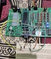
I am attaching picture for pull up resistor. And I hope all the connection I hame are correct
Resistor 4k7
Attachments
-
 4.3 MB Views: 16
The picture is kind of hard to follow because the wires obscure some of the connections but its looks right assuming you have found the right PIC pins for SDA and SCL on the header.Hi
I am attaching picture for pull up resistor. And I hope all the connection I hame are correct
Resistor 4k7
Here is program for I2CThe picture is kind of hard to follow because the wires obscure some of the connections but its looks right assuming you have found the right PIC pins for SDA and SCL on the header.
C:
#define _XTAL_FREQ 20000000     // crystal 20MHz
// PIC18F45K80 Configuration Bit Settings
// CONFIG1L
#pragma config RETEN = ON       // VREG Sleep Enable bit (Ultra low-power regulator is Enabled (Controlled by SRETEN bit))
#pragma config INTOSCSEL = LOW  // LF-INTOSC Low-power Enable bit (LF-INTOSC in Low-power mode during Sleep)
// SOSCSEL = No Setting
#pragma config XINST = OFF      // Extended Instruction Set (Disabled)
// CONFIG1H
#pragma config FOSC = HS2       // HS oscillator (high power, 16 MHz-25 MHz
#pragma config PLLCFG = OFF     // PLL x4 Enable bit (Disabled)
#pragma config FCMEN = OFF      // Fail-Safe Clock Monitor (Disabled)
#pragma config IESO = OFF       // Internal External Oscillator Switch Over Mode (Disabled)
// CONFIG2L
#pragma config PWRTEN = ON      // Power Up Timer (Enabled)
#pragma config BOREN = OFF      // Brown Out Detect (Disabled in hardware, SBOREN disabled)
#pragma config BORV = 0         // Brown-out Reset Voltage bits (3.0V)
#pragma config BORPWR = LOW     // BORMV Power level (BORMV set to low power level)
// CONFIG2H
#pragma config WDTEN = OFF      // Watchdog Timer (WDT disabled in hardware; SWDTEN bit disabled)
#pragma config WDTPS = 1        // Watchdog Postscaler (1:1)
// CONFIG3H
#pragma config CANMX = PORTC    // ECAN Mux bit (ECAN TX and RX pins are located on RC6 and RC7, respectively)
#pragma config MSSPMSK = MSK5   // MSSP address masking (5 bit address masking mode)
#pragma config MCLRE = ON      // Master Clear Enable (MCLR Enabled, RE3 Disabled)
// CONFIG4L
#pragma config STVREN = OFF     // Stack Overflow Reset (Disabled)
#pragma config BBSIZ = BB1K     // Boot Block Size (1K word Boot Block size)
// CONFIG5L
#pragma config CP0 = ON         // Code Protect 00800-01FFF (Enabled)
#pragma config CP1 = ON         // Code Protect 02000-03FFF (Enabled)
#pragma config CP2 = ON         // Code Protect 04000-05FFF (Enabled)
#pragma config CP3 = ON         // Code Protect 06000-07FFF (Enabled)
// CONFIG5H
#pragma config CPB = ON         // Code Protect Boot (Enabled)
#pragma config CPD = ON         // Data EE Read Protect (Enabled)
// CONFIG6L
#pragma config WRT0 = ON        // Table Write Protect 00800-01FFF (Enabled)
#pragma config WRT1 = ON        // Table Write Protect 02000-03FFF (Enabled)
#pragma config WRT2 = ON        // Table Write Protect 04000-05FFF (Enabled)
#pragma config WRT3 = ON        // Table Write Protect 06000-07FFF (Enabled)
// CONFIG6H
#pragma config WRTC = ON        // Config. Write Protect (Enabled)
#pragma config WRTB = ON        // Table Write Protect Boot (Enabled)
#pragma config WRTD = ON        // Data EE Write Protect (Enabled)
// CONFIG7L
#pragma config EBTR0 = ON       // Table Read Protect 00800-01FFF (Enabled)
#pragma config EBTR1 = ON       // Table Read Protect 02000-03FFF (Enabled)
#pragma config EBTR2 = ON       // Table Read Protect 04000-05FFF (Enabled)
#pragma config EBTR3 = ON       // Table Read Protect 06000-07FFF (Enabled)
// CONFIG7H
#pragma config EBTRB = ON       // Table Read Protect Boot (Enabled)
// #pragma config statements should precede project file includes.
// Use project enums instead of #define for ON and OFF.
#include <xc.h>
#define IN1307_ADDR 0xD0    //I2C slave address of DS1307 (8 bit format)
#define SECONDS_REG 0   //offset of the "seconds" register in the DS1307
void Port_Initialized (void)
{
    ANCON0 = 0;    // digital
    ANCON1 = 0;    // Set to digital port
    CM1CON = 0;      // Comparator off
    CM2CON = 0;      // Comparator off
    ADCON0 = 0;      // A/D conversion Disabled
    ADCON1 = 0;      // A/D conversion Disabled
    ADCON2 = 0;     // A/D conversion Disabled

    LATA =  0;
    LATB =  0;
    LATC =  0;
    LATD =  0;
    LATE =  0;

    TRISA = 0b0000000;    // AN0 as input,
    TRISB = 0b0000000;   // all are output, Unused
  //  TRISC = 0b0001100;   //
    TRISD = 0b0000000;   // all are output, Unused
    TRISE = 0b0000000;   // All are output, Unused
}
//Initialize I2C in master mode, Sets the required baudrate
void I2C_Init(void)
{
     TRISCbits.TRISC3 = 1;
     TRISCbits.TRISC4 = 1;
    SSPSTAT=0x80; //Slew rate control is disabled for Standard Speed mode (100 kHz and 1 MHz)
    SSPCON1=0x28; // I2C Master mode, clock = FOSC/(4 * (SSPADD + 1))
    SSPCON2=0x00;
    SSPADD = 49;    //100kHz clock @ 20MHz Fosc
}
// Send an I2C START
// Return 0 if all ok, 1 if bus collision
__bit I2C_Start(void)
{
    BCLIF = 0;  //Clear 'Bus collision" flag
    SEN = 1;    //initiate a START cycle
    while (SEN);    //wait until it has been sent
    return BCLIF;   //return value of BCLIF flag
}
// Send an I2C STOP
void I2C_Stop(void)
{
    PEN = 1;    //initiate a STOP cycle
    while (PEN);    //wait until it has been sent
}
// Send an I2C REPEATED START
void I2C_Restart(void)
{
    RSEN = 1;    //initiate a REPEATED START cycle
    while (RSEN);    //wait until it has been sent
}
//Send one byte. Return 0 if ACK received, or 1 if NAK received
__bit I2C_Sendbyte(unsigned char dat)
{
    SSPBUF = dat;
    while (R_W);    //wait until byte sent and ACK/NAK received
    return ACKSTAT;
}
//Receive one byte. ackflag=0 to send ACK, or 1 to send NAK in reply
unsigned char I2C_Recvbyte(unsigned char ackflag)
{
    RCEN = 1;   // initiate a RECEIVE cycle
    ACKDT = ackflag;    //specify if we should send ACK or NAK after receiving
    while (RCEN);   //wait until RECEIVE has completed
    ACKEN = 1;  //initiate an ACK cycle
    while (ACKEN);  //wait until it has completed
    return SSPBUF;
}
//Send an array of data to an I2C device.
//Return 0 if all OK, 1 if bus error, 2 if slave address NAK, 3 if slave register NAK, 4 if slave data NAK
unsigned char I2C_Writeblock(unsigned char slave_address, unsigned char start_reg, unsigned char buflen, const unsigned char * bufptr)
{
    if (I2C_Start() )   //send a start, and check if it succeeded
        return 1;   //abort if bus collision
    //send the I2C slave address (force R/W bit low)
    if (I2C_Sendbyte(slave_address & 0xFE))
    {
        I2C_Stop(); //if address was NAKed, terminate the cycle
        return 2;   //and return error code
    }
    //send the device register index
    if (I2C_Sendbyte(start_reg))
    {
        I2C_Stop(); //if register was NAKed, terminate the cycle
        return 3;   //and return error code
    }
    //send the data. buflen might be zero!
    for (; buflen>0; --buflen)
    {
        if (I2C_Sendbyte(*bufptr++))
        {
            I2C_Stop(); //if register was NAKed, terminate the cycle
            return 4;   //and return error code
        }

    }
    I2C_Stop();
    return 0;   //no error
}
//Receive an array of data from an I2C device.
//Return 0 if all OK, 1 if bus error, 2 if slave address NAK, 3 if slave register NAK
unsigned char I2C_Readblock(unsigned char slave_address, unsigned char start_reg, unsigned char buflen, unsigned char * bufptr)
{
    //do a dummy zero length write cycle to set the register address
    unsigned char retval = I2C_Writeblock(slave_address, start_reg,0,0);
    if (retval)
    {
        return retval;  //abort if there was an error
    }
    //now start the READ cycle
    if (I2C_Start() )   //send a start, and check if it succeeded
        return 1;   //abort if bus collision
    //send the I2C slave address (force the R/W bit high)
    if (I2C_Sendbyte(slave_address | 0x01))
    {
        I2C_Stop(); //if address was NAKed, terminate the cycle
        return 2;   //and return error code
    }
    //receive the data.
    for (; buflen>0; --buflen)
    {
        unsigned char ackflag = (buflen == 1);   //1 if this is the last byte to receive => send NAK
        *bufptr++ = I2C_Recvbyte(ackflag);
    }
    I2C_Stop();
    return 0;   //no error
}
const unsigned char rtc_data[] =
{
    0x56,   //56 seconds
    0x34,   //34 minutes
    0x12,   //12 hours & 24 hour mode
    0x01,   //01 day=Sunday
    0x03,   //03 date
    0x12,   //12 month=dec
    0x01,   //01 year=2001
};
unsigned char rd_buf[7];
void main(void) {
    I2C_Init();
    unsigned char w;
    unsigned char r;

    w = I2C_Writeblock(IN1307_ADDR, SECONDS_REG, sizeof(rtc_data), rtc_data);
    r = (I2C_Readblock(IN1307_ADDR, SECONDS_REG, sizeof(rd_buf), rd_buf) );

    while(1);   //endless loop to avoid exiting main() function)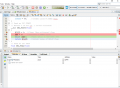
}When I debug code I never see any value on PORTC. Code stuck at line 95 while (SEN); //wait until it has been sent (I2C start function )
Attachments
-
 77.3 KB Views: 8

It was my mistake Nothing is connected to port AWhat is connected to PORTA,0?
View attachment 221599
PORTA is an 8-bit port, why are you only setting 7 of those bits. None are set to input. Check your other ports too.
C:
#define _XTAL_FREQ 20000000     // crystal 20MHz
// PIC18F45K80 Configuration Bit Settings
// CONFIG1L
#pragma config RETEN = ON       // VREG Sleep Enable bit (Ultra low-power regulator is Enabled (Controlled by SRETEN bit))
#pragma config INTOSCSEL = LOW  // LF-INTOSC Low-power Enable bit (LF-INTOSC in Low-power mode during Sleep)
// SOSCSEL = No Setting
#pragma config XINST = OFF      // Extended Instruction Set (Disabled)
// CONFIG1H
#pragma config FOSC = HS2       // HS oscillator (high power, 16 MHz-25 MHz
#pragma config PLLCFG = OFF     // PLL x4 Enable bit (Disabled)
#pragma config FCMEN = OFF      // Fail-Safe Clock Monitor (Disabled)
#pragma config IESO = OFF       // Internal External Oscillator Switch Over Mode (Disabled)
// CONFIG2L
#pragma config PWRTEN = ON      // Power Up Timer (Enabled)
#pragma config BOREN = OFF      // Brown Out Detect (Disabled in hardware, SBOREN disabled)
#pragma config BORV = 0         // Brown-out Reset Voltage bits (3.0V)
#pragma config BORPWR = LOW     // BORMV Power level (BORMV set to low power level)
// CONFIG2H
#pragma config WDTEN = OFF      // Watchdog Timer (WDT disabled in hardware; SWDTEN bit disabled)
#pragma config WDTPS = 1        // Watchdog Postscaler (1:1)
// CONFIG3H
#pragma config CANMX = PORTC    // ECAN Mux bit (ECAN TX and RX pins are located on RC6 and RC7, respectively)
#pragma config MSSPMSK = MSK5   // MSSP address masking (5 bit address masking mode)
#pragma config MCLRE = ON      // Master Clear Enable (MCLR Enabled, RE3 Disabled)
// CONFIG4L
#pragma config STVREN = OFF     // Stack Overflow Reset (Disabled)
#pragma config BBSIZ = BB1K     // Boot Block Size (1K word Boot Block size)
// CONFIG5L
#pragma config CP0 = ON         // Code Protect 00800-01FFF (Enabled)
#pragma config CP1 = ON         // Code Protect 02000-03FFF (Enabled)
#pragma config CP2 = ON         // Code Protect 04000-05FFF (Enabled)
#pragma config CP3 = ON         // Code Protect 06000-07FFF (Enabled)
// CONFIG5H
#pragma config CPB = ON         // Code Protect Boot (Enabled)
#pragma config CPD = ON         // Data EE Read Protect (Enabled)
// CONFIG6L
#pragma config WRT0 = ON        // Table Write Protect 00800-01FFF (Enabled)
#pragma config WRT1 = ON        // Table Write Protect 02000-03FFF (Enabled)
#pragma config WRT2 = ON        // Table Write Protect 04000-05FFF (Enabled)
#pragma config WRT3 = ON        // Table Write Protect 06000-07FFF (Enabled)
// CONFIG6H
#pragma config WRTC = ON        // Config. Write Protect (Enabled)
#pragma config WRTB = ON        // Table Write Protect Boot (Enabled)
#pragma config WRTD = ON        // Data EE Write Protect (Enabled)
// CONFIG7L
#pragma config EBTR0 = ON       // Table Read Protect 00800-01FFF (Enabled)
#pragma config EBTR1 = ON       // Table Read Protect 02000-03FFF (Enabled)
#pragma config EBTR2 = ON       // Table Read Protect 04000-05FFF (Enabled)
#pragma config EBTR3 = ON       // Table Read Protect 06000-07FFF (Enabled)
// CONFIG7H
#pragma config EBTRB = ON       // Table Read Protect Boot (Enabled)
// #pragma config statements should precede project file includes.
// Use project enums instead of #define for ON and OFF.
#include <xc.h>
#define IN1307_ADDR 0xD0    //I2C slave address of DS1307 (8 bit format)
#define SECONDS_REG 0   //offset of the "seconds" register in the DS1307
void Port_Initialized (void)
{
    ANCON0 = 0;    // digital
    ANCON1 = 0;    // Set to digital port
    CM1CON = 0;      // Comparator off
    CM2CON = 0;      // Comparator off
    ADCON0 = 0;      // A/D conversion Disabled
    ADCON1 = 0;      // A/D conversion Disabled
    ADCON2 = 0;     // A/D conversion Disabled

    LATA =  0;
    LATB =  0;
    LATC =  0;
    LATD =  0;
    LATE =  0;

    TRISA = 0b00000000;    // all are output unused
    TRISB = 0b00000000;   // all are output, Unused   //
    TRISD = 0b00000000;   // all are output, Unused
    TRISE = 0b00000000;   // All are output, Unused
}
//Initialize I2C in master mode, Sets the required baudrate
void I2C_Init(void)
{
     TRISCbits.TRISC3 = 1;
     TRISCbits.TRISC4 = 1;
    SSPSTAT=0x80; //Slew rate control is disabled for Standard Speed mode (100 kHz and 1 MHz)
    SSPCON1=0x28; // I2C Master mode, clock = FOSC/(4 * (SSPADD + 1))
    SSPCON2=0x00;
    SSPADD = 49;    //100kHz clock @ 20MHz Fosc
}
// Send an I2C START
// Return 0 if all ok, 1 if bus collision
__bit I2C_Start(void)
{
    BCLIF = 0;  //Clear 'Bus collision" flag
    SEN = 1;    //initiate a START cycle
    while (SEN);    //wait until it has been sent
    return BCLIF;   //return value of BCLIF flag
}
// Send an I2C STOP
void I2C_Stop(void)
{
    PEN = 1;    //initiate a STOP cycle
    while (PEN);    //wait until it has been sent
}
// Send an I2C REPEATED START
void I2C_Restart(void)
{
    RSEN = 1;    //initiate a REPEATED START cycle
    while (RSEN);    //wait until it has been sent
}
//Send one byte. Return 0 if ACK received, or 1 if NAK received
__bit I2C_Sendbyte(unsigned char dat)
{
    SSPBUF = dat;
    while (R_W);    //wait until byte sent and ACK/NAK received
    return ACKSTAT;
}
//Receive one byte. ackflag=0 to send ACK, or 1 to send NAK in reply
unsigned char I2C_Recvbyte(unsigned char ackflag)
{
    RCEN = 1;   // initiate a RECEIVE cycle
    ACKDT = ackflag;    //specify if we should send ACK or NAK after receiving
    while (RCEN);   //wait until RECEIVE has completed
    ACKEN = 1;  //initiate an ACK cycle
    while (ACKEN);  //wait until it has completed
    return SSPBUF;
}
//Send an array of data to an I2C device.
//Return 0 if all OK, 1 if bus error, 2 if slave address NAK, 3 if slave register NAK, 4 if slave data NAK
unsigned char I2C_Writeblock(unsigned char slave_address, unsigned char start_reg, unsigned char buflen, const unsigned char * bufptr)
{
    if (I2C_Start() )   //send a start, and check if it succeeded
        return 1;   //abort if bus collision
    //send the I2C slave address (force R/W bit low)
    if (I2C_Sendbyte(slave_address & 0xFE))
    {
        I2C_Stop(); //if address was NAKed, terminate the cycle
        return 2;   //and return error code
    }
    //send the device register index
    if (I2C_Sendbyte(start_reg))
    {
        I2C_Stop(); //if register was NAKed, terminate the cycle
        return 3;   //and return error code
    }
    //send the data. buflen might be zero!
    for (; buflen>0; --buflen)
    {
        if (I2C_Sendbyte(*bufptr++))
        {
            I2C_Stop(); //if register was NAKed, terminate the cycle
            return 4;   //and return error code
        }

    }
    I2C_Stop();
    return 0;   //no error
}
//Receive an array of data from an I2C device.
//Return 0 if all OK, 1 if bus error, 2 if slave address NAK, 3 if slave register NAK
unsigned char I2C_Readblock(unsigned char slave_address, unsigned char start_reg, unsigned char buflen, unsigned char * bufptr)
{
    //do a dummy zero length write cycle to set the register address
    unsigned char retval = I2C_Writeblock(slave_address, start_reg,0,0);
    if (retval)
    {
        return retval;  //abort if there was an error
    }
    //now start the READ cycle
    if (I2C_Start() )   //send a start, and check if it succeeded
        return 1;   //abort if bus collision
    //send the I2C slave address (force the R/W bit high)
    if (I2C_Sendbyte(slave_address | 0x01))
    {
        I2C_Stop(); //if address was NAKed, terminate the cycle
        return 2;   //and return error code
    }
    //receive the data.
    for (; buflen>0; --buflen)
    {
        unsigned char ackflag = (buflen == 1);   //1 if this is the last byte to receive => send NAK
        *bufptr++ = I2C_Recvbyte(ackflag);
    }
    I2C_Stop();
    return 0;   //no error
}
const unsigned char rtc_data[] =
{
    0x56,   //56 seconds
    0x34,   //34 minutes
    0x12,   //12 hours & 24 hour mode
    0x01,   //01 day=Sunday
    0x03,   //03 date
    0x12,   //12 month=dec
    0x01,   //01 year=2001
};
unsigned char rd_buf[7];
void main(void) {
    I2C_Init();
    unsigned char w;
    unsigned char r;

    w = I2C_Writeblock(IN1307_ADDR, SECONDS_REG, sizeof(rtc_data), rtc_data);
    r = (I2C_Readblock(IN1307_ADDR, SECONDS_REG, sizeof(rd_buf), rd_buf) );

    while(1);   //endless loop to avoid exiting main() function)
}Are you running the simulator or the actual chip hardware? (The simulator does not simulate the MSSP),
The setup looks OK. Be sure that both SCL and SDA are '1' when you break on entering I2C_Start. Measure the voltage at the pins AND examine PORTC in the SFR window - both SCL and SDA should be 0. Then break at while(SEN) and see if SCL and SDA are now '0' (examine the SFR window too). If both are 0, the Start has been sent.
If it were me, I would remove both of the I2C chips from their sockets and get to the point where I could sent Start, slave address, get the NAK (from no chips) and send stoP, leaving the bus at 1,1 (idle). When you get that far, put in one chip and go from there. You want to avoid any issues from the chips while you are debugging the basics.
I'm not real familiar with the master mode so might have missed something.
ALSO: you are not calling PortInitialize() - that was in the compiler warnings....
Last edited:
morning JohanInTXAre you running the simulator or the actual chip hardware? (The simulator does not simulate the MSSP),
I am running code on actual hardware chip
I don't understand this process so if I remove both PIC18f45k80 and IN1307 from the chip How the test will happenIf it were me, I would remove both of the I2C chips from their sockets and get to the point where I could sent Start, slave address, get the NAK (from no chips) and send stoP, leaving the bus at 1,1 (idle). When you get that far, put in one chip and go from there. You want to avoid any issues from the chips while you are debugging the basics.
That code does not work.
Attached is working hex file. Connect 4 on-board LEDs to PIC D0, D1, D2, D3
If the LEDs count up once per second - hardware is working.
Attached is working hex file. Connect 4 on-board LEDs to PIC D0, D1, D2, D3
If the LEDs count up once per second - hardware is working.
Attachments
-
10.1 KB Views: 2
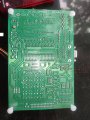
@JohnInTX @hexreader There is no pull up resistors on the board for IN1307. and I don't have resistor bank I have only two 4.7 K resistorThe picture is kind of hard to follow because the wires obscure some of the connections but its looks right assuming you have found the right PIC pins for SDA and SCL on the header.
I have soldered both of them on my board I am supplying 5V DC to them Will they work ?

I am attaching both front and back picture
Attachments
-
 3 MB Views: 4
What you show is correct.
If you want to use SQW (Square Wave Output) in the future, then you will need a third resistor. You do not need it for your current project.
Those 4 holes are for fitting a 4-pin resistor pack (containing 3 resistors).
You can make your own resistor pack as shown in the attached picture.
If you want to use SQW (Square Wave Output) in the future, then you will need a third resistor. You do not need it for your current project.
Those 4 holes are for fitting a 4-pin resistor pack (containing 3 resistors).
You can make your own resistor pack as shown in the attached picture.
Attachments
-
 160.4 KB Views: 9
@hexreader Thank you for clarification Do you have DS1307 RTC ?What you show is correct.
Edit : I am struggling with code
@hexreader Thanks. Can you post your c code with comments, not a hex file ?Yes, I have DS1307 and PIC18F45K80.
I use mikroC compiler and library.
I think I already provided mikroC code in post #134
RTC2read.c
It uses libraries, so probably will not help you
Header comments suggest PIC18F4620 - just ignore that comment, the project is for PIC18F45K80.
Ignore the LCD code - it is harmless.
Connect terminal to UART RC6, RC7 9600,8,n,1 to see time update every second
RTC2read.c
It uses libraries, so probably will not help you
Header comments suggest PIC18F4620 - just ignore that comment, the project is for PIC18F45K80.
Ignore the LCD code - it is harmless.
Connect terminal to UART RC6, RC7 9600,8,n,1 to see time update every second
Last edited:


