 Facebook
 Google
 GitHub
 Linkedin
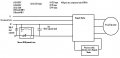
I built a phase converter to convert single phase 240v 60hz (2 hot wire and ground) to three phase 240v 60 hz (3 hot wires L1, L2, L3 and a ground).
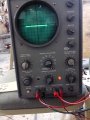
I want to the check the phase shift using the Lissajous method on my old Eico 427 Scope (similar to Eico 460). There is no XY mode.
I'm using unshielded banana leads with alligator clips. There are 5 jacks on the machine. Say I want to check the phase shift between L1 and L3 for example.
What are the proper jacks to attach the leads to?
How many leads do I use?
What spot should the sync selector and the sweep selector be?
The manual is here: http://bama.edebris.com/manuals/eico/460/
Pg. 7 of the pdf file describes the measurement somewhat.
I have attach a photo of the face of the scope. The knob at the top right is intensity.
The rings around the knobs also turn to for further adjustments.
Attachments
-
 790.5 KB Views: 44
")


