Facebook
 Google
 GitHub
 Linkedin
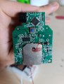
Goodmorning, I'm working on a project for my studies in electronic engineering, I am looking at a PCB of a qr scanner and trying to debug it in order to use it with a microcontroller (esp32). The output of the scanner is usually taken from a usb port, but on the PCB there are also 4 others pin which I don't understand what they represent. The pins are 3.3V, GND (which are obvious), c and d. Anybody can explain me, in his opinion, c and d which protocol represent? (UART, I2c, ...). I know that it really depends on the design of the product, which has other purposes and it is hard to act on it, but maybe there is a suggestion from some hobbyist that encountered this problem.
I tried using it straight connected to the esp32 as if it uses a uart, but I was not lucky.
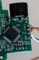
Attached a photo of the circuit
I tried using it straight connected to the esp32 as if it uses a uart, but I was not lucky.
Attached a photo of the circuit
Attachments
-
 324.5 KB Views: 8