Facebook
 Google
 GitHub
 Linkedin
Hello all,
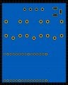
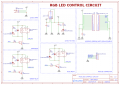
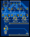
I've recently completed the design of a circuit schematic and PCB for controlling an RGB LED string using a NodeMCU ESP8266 WiFi module. The circuit operates on a 12V DC input and utilizes three relays to control the red, blue, and green LEDs respectively. The LED string itself draws approximately 14.4W per meter, and I plan to power a 5-meter long string, resulting in a total current draw of 6A.
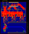
In order to ensure proper operation, I used an online PCB trace calculator to determine the required trace widths for the PCB. Utilizing a 1oz copper weight, the outer layer traces should be wider than 3.56mm to handle the current load effectively. Therefore, I used 4mm trace widths for powering the LED string. It might be a overkill since each relay powers up one third of the total requirement but ı wanted the power line to be safe.
I used bottom layer as GND.
I am open to receive feedback and suggestions for potential improvements or any oversights.
Thank you all.
I've recently completed the design of a circuit schematic and PCB for controlling an RGB LED string using a NodeMCU ESP8266 WiFi module. The circuit operates on a 12V DC input and utilizes three relays to control the red, blue, and green LEDs respectively. The LED string itself draws approximately 14.4W per meter, and I plan to power a 5-meter long string, resulting in a total current draw of 6A.
In order to ensure proper operation, I used an online PCB trace calculator to determine the required trace widths for the PCB. Utilizing a 1oz copper weight, the outer layer traces should be wider than 3.56mm to handle the current load effectively. Therefore, I used 4mm trace widths for powering the LED string. It might be a overkill since each relay powers up one third of the total requirement but ı wanted the power line to be safe.
I used bottom layer as GND.
I am open to receive feedback and suggestions for potential improvements or any oversights.
Thank you all.
Attachments
-
 115 KB Views: 15
 -
 53.5 KB Views: 13
 -
 79 KB Views: 12