PCB frying DC-DC converter and relays sticking on- back EMF?

panic mode

Joined Oct 10, 2011
5,185
you need to get some numbers first. looking at the circuit i am estimating current draw in the 100mA (0.1A).
at 12V that is equivalent to 100-120 Ohm load.
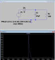
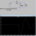
adding LC filter where
L=20mH, max 3A, 500mOhm
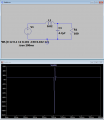
and C = 4.7uF it is easy to see that 1ms long -150V transient will not get diminished
1698702654409.png

increasing capacitor value by three orders of magnitude does help. At least it gets you into range where voltage regulator is surviving.
1698702712054.png

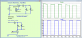
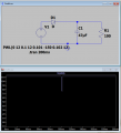
but that inductor and capacitor are rather bulky. simple diode would completely get rid of any harm due to negative transients. (and that is what inductive loads produce when you turn them off). and with a small capacitor it would not even register. This still would not solve sticky relay contacts (which is why you should have diodes also across relay contacts)
1698703463235.png

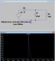
the problem however remains for positive transients (load dump). those are positive (so diode will not help) and worse - they have more energy (last much longer but not as steep). so for this adding LC like in second example would help. cheaper and more compact solution would be a crow bar (zener and large transistor or SCR or whatever).
1698704031471.png

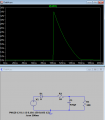
btw low R of inductor is not going to change much. even if it 2-3 Ohm, at current of 100mA that is only voltage drop of 0.2-0.3V. so why not add a resistor... on purpose?

for example using diode, 10 Ohm 2W resistor and 470uF capacitor would mean there is a supply voltage drop of about 1.6V but your circuit would be happy and the positive transients would be absorbed a lot better. and you could put two such caps in parallel. of course using inductor instead of resistor is better. (inductors and capacitors are storage devices and losses are small).

and if your target platform does not have other devices that could dump the load, this would not even be an issue.
1698704530509.png
 

Attachments

Last edited:

MisterBill2

Joined Jan 23, 2018
28,055
OK, certainly the choke could have a lot more inductance, I did not do the math at the time. and a diode across the line to clamp any negative spikes would be simple to add.
The main point is that a series reactance can do much more towardreducing transients than a shunt reactance that is functionally a voltage divider. The limiting factors are the inductor resistance and the cost.
 

Thread Starter

htdave

Joined Oct 26, 2023
16
So I finally got an oscilloscope.

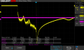
In the below image, yellow is the voltage of my relay output, and pink is the input voltage of my cubecell module (meant to be 3.3V)

It's a bit hard to see in the picture, but there is a pink voltage spike, that coincides with the yellow voltage spike.

The relay output is peaking at about -330V, and oscillates with a time period of about 100nS.
The cubecell voltage peaks at about -15V.

Putting a diode between my relay outputs does nothing to reduce these voltage spikes.
If I put a 100uF capacitor between relay output and GND, it drastically reduces the yellow voltage spike, and completely eliminates the pink voltage spikes.

Whilst the capacitor solves the issue, I'm not convinced that it is the correct way to deal with the reverse voltage, so I am after suggestions on how it should be done.

Thanks

SDS00002.png
 

MisterBill2

Joined Jan 23, 2018
28,055
The main down-side of putting a capacitor directly across the relay contacts is that when the contacts are open the capacitor charges and then it dumps that charge into the contacts when the relay closes. So try a ten ohm resistor in series with the capacitor, or maybe a 4R7 (4.7 OHM) RESISTOR IN SERIES WITH THE CAPACITOR. That will greatly reduce the current. Use at least a half watt resistor.
 

Thread Starter

htdave

Joined Oct 26, 2023
16
The main down-side of putting a capacitor directly across the relay contacts is that when the contacts are open the capacitor charges and then it dumps that charge into the contacts when the relay closes. So try a ten ohm resistor in series with the capacitor, or maybe a 4R7 (4.7 OHM) RESISTOR IN SERIES WITH THE CAPACITOR. That will greatly reduce the current. Use at least a half watt resistor.
The capacitor is between the relay output (12V) and GND, not between the relay contacts
 

Thread Starter

htdave

Joined Oct 26, 2023
16
I've never really seen capacitors used in conjunction with relays.
What do you suggest to handle the voltage spikes of the inductive load?
I tried a diode across the relay contacts, but it made no difference. Do I need to use an ultrafast or Schottky diode since the resonance seems to be about 100nS?
 

Papabravo

Joined Feb 24, 2006
22,105
What do you suggest to handle the voltage spikes of the inductive load?
I tried a diode across the relay contacts, but it made no difference. Do I need to use an ultrafast or Schottky diode since the resonance seems to be about 100nS?
If you are going to use a diode is should be across the inductor. It should be connected so that it is not forward biased when the coil is energized.

Like this:

1700776990900.png

Look Ma! No capacitors.
Certainly nothing across the switch contacts either.
 
Last edited:

Thread Starter

htdave

Joined Oct 26, 2023
16
If you are going to use a diode is should be across the inductor. It should be connected so that it is not forward biased when the coil is energized.

Like this:

View attachment 308266

Look Ma! No capacitors.
Certainly nothing across the switch contacts either.
Not sure why I didn't think of that originally!.

I have just tried putting a diode across the inductor, and the negative voltage peaks at about -2.3V, which I can live with.

Thanks for your help
 

Papabravo

Joined Feb 24, 2006
22,105
The MBR745 is a Schottky Diode which will limit the excursions outside the supply range to several hundred millivolts. Try to get one of those if you can.
 

MisterBill2

Joined Jan 23, 2018
28,055
I don't think you want them there either. I've never seen that done before.
Most often the capacitor across contacts also has a series resistor, and it is called a SNUBBER. And the ONLY place it will be effective is across the contacts. It can not be effective any place else. The capacitor slows the current rate of change by charging to the voltage in a standard RC time constant manner. And a capacitor is exactly the device most suited for the application. The low value series resistor is to reduce the current and spark when the contacts close with the caoacitor charged.
 

Papabravo

Joined Feb 24, 2006
22,105
Most often the capacitor across contacts also has a series resistor, and it is called a SNUBBER. And the ONLY place it will be effective is across the contacts. It can not be effective any place else. The capacitor slows the current rate of change by charging to the voltage in a standard RC time constant manner. And a capacitor is exactly the device most suited for the application. The low value series resistor is to reduce the current and spark when the contacts close with the caoacitor charged.
Most of my experience with relays is for industrial control using ladder logic. I have never seen capacitors across contacts in this environment, unless perhaps industrial relays have them internally.
 

MaxHeadRoom

Joined Jul 18, 2013
30,772
Most of my experience with relays is for industrial control using ladder logic. I have never seen capacitors across contacts in this environment, unless perhaps industrial relays have them internally.
As I posted, I have used the variety that uses a blow-out magnet for high current switching mounted close to the contacts, quite effective and non-invasive!
 

MisterBill2

Joined Jan 23, 2018
28,055
Most of my experience with relays is for industrial control using ladder logic. I have never seen capacitors across contacts in this environment, unless perhaps industrial relays have them internally.
Both of the relays are controlling fairly large inductive loads. Not at all like CNC systems used in industry. Snubbers are used quite a bit to protect relay contacts, and switch contacts, feeding inductive loads.
 

Papabravo

Joined Feb 24, 2006
22,105
Both of the relays are controlling fairly large inductive loads. Not at all like CNC systems used in industry. Snubbers are used quite a bit to protect relay contacts, and switch contacts, feeding inductive loads.
There must be some ambiguity in the use of the snubbers if the TS was doing it a way that damaged his parts.
 

MaxHeadRoom

Joined Jul 18, 2013
30,772
Most of my experience with relays is for industrial control using ladder logic. I have never seen capacitors across contacts in this environment, unless perhaps industrial relays have them internally.
If switching high DC voltage and/or current levels, a capacitor should never be used, it will prolong any arc.
I have seen contacts completely burnt off due to the plasma arc effect.
With no means of suppression, the arc continues after the contacts are open, this is the very principle that plasma cutting operations use. o_O
 

MisterBill2

Joined Jan 23, 2018
28,055
An adequate capacitor across relay contacts will present a very low impedance at the instant the contacts are opened, which tends very much to reduce the tendency to arc,, because it reduces the voltage across the contacts as it accepts charge. That is rather basic and independent of the voltage. A SNUBBER also includes a resistance to limit the current from the capacitor discharge when the contacts close.
So please describe the process of prolonging an arc by shunting the contacts with a capacitor that is fully discharged prior to those contacts opening. Usually the voltage across closed contacts is very low.
 
Top