PCB frying DC-DC converter and relays sticking on- back EMF?

Thread Starter

htdave

Joined Oct 26, 2023
16
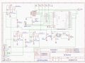
I have a PCB that is giving occasional problems.

The circuit is a remote receiver, based on the Heltec Cubcell Module. Basically, it will turn up to 3 relays on, depending on the signal it receives from the transmitters.

The circuit is powered from 12VDC, suppllied by a lead acid battery, which is charged by a stationary engine - simmilar to a rideon lawn mower setup.

2 of the 3 relays power up an electric clutch (max current draw 4.7A), while the 3rd relay powers up a small solenoid (~2A draw)

We tested some prototypes, and all appeared to work well, so we went ahead with a production run of about 30 boards.

Most boards appear to be working well, however, we have had a few boards that have blown up the DC-DC converter, and a couple of boards that a relay is sticking on.

I am a complete novice when it comes to electronic circuit design (I am a mechanical engineer), so am looking for any suggestions on what might be happening, or what could be improved in the circuit.

My only guess is that there could be a back EMF caused by the starter motor of the engine, or the electric clutches, that is potentially killing the DC-DC converter, or maybe the transistor.

In the case of DC-DC failure, sometimes the chip is visually blown, and other times, everything looks okay, but it does not output any voltage.

In the case of the relay sticking on, the only logical reason I can see is a faulty transistor, but I am unsure how to test the transistors.

Any help would be much appreciated, and apologies if this is in the wrong place
 

Attachments

crutschow

Joined Mar 14, 2008
38,316
For the relays you could add a suppression diode across the contacts, the same as across the coil.
An inductive load can generate large inductive arcing across contacts, which can cause them to weld together.

Not sure what might be blowing the converters.
What is the current rating of the converter, and what's its maximum load current?
 

Thread Starter

htdave

Joined Oct 26, 2023
16
For the relays you could add a suppression diode across the contacts, the same as across the coil.
An inductive load can generate large inductive arcing across contacts, which can cause them to weld together.

Not sure what might be blowing the converters.
What is the current rating of the converter, and what's its maximum load current?
Would the diode be best between pin 3 & 4 of the relay, or Pin 3 & GND?

The converter is rated to 2A continuous. Max the circuit should draw would be about 500mA
 

MisterBill2

Joined Jan 23, 2018
27,173
OK,I have some thoughts and a few questions: what is the current rating for the relay contacts? and the voltage rating? Next, are you aware that putting a diode across the relay coil slows the release time quite a bit? And relay contact arcing happens mostly as the relay contact is opening and interrupting the current. THAT will certainly lead to relay sticking, but not right away.
The DC to DC converter appears to be directly connected to that same power buss that feeds the relays and the clutches and whatever else may be connected to the battery . There should be a bit of filtering of that Vcc line, before the supply reaches C7. An inductance plus another capacitor, about 0.1 mFd across the VCC to common near the converter.
Instead of diodes across the relay coils, use transistors rated for a higher voltage, maybe 200 volts Vce, and get rid of the diodes which assure plenty of time for the arcing while the relay releases.
 

crutschow

Joined Mar 14, 2008
38,316
putting a diode across the relay coil slows the release time quite a bit? And relay contact arcing happens mostly as the relay contact is opening and interrupting the current. THAT will certainly lead to relay sticking, but not right away.
I disagree.
The diode slows down the time it takes for the relay to release, but does not significantly reduce the time for the contacts to release which occurs when the coil current has reached a low current level.
The contact movement time is not a linear (or significant) function of magnetic strength.
The contact release is a mechanical (rather snap-action) function mainly determined by the contact inertia and spring strength.
Instead of diodes across the relay coils, use transistors rated for a higher voltage,
If you really want to reduce the relay delay then just add a Zener or resistor of appropriate resistance in series with the diode.
That will still protect the driver while reducing the delay.
 

eetech00

Joined Jun 8, 2013
4,704
There is a diode suppressor across each relay coil...that is good.
What is the purpose of Pin 4 and Pin 2 of "Switch Plug"?

There may be EMF coming from the motor. What type of motor? P/N?
 

MisterBill2

Joined Jan 23, 2018
27,173
If you don't mind the relays sticking then go right ahead and keep the diodes in. Higher voltage rated transistors are a better alternative. And keeping assorted transients out of the DC/DC supply should prevent the failures.
 

MisterBill2

Joined Jan 23, 2018
27,173
If you mean can I reference technical research articles published, no. But I have observed relays in various applications and observed that the release of some forms of contacts involves the one contact sliding a very small distance across the surface of the fixed contact, producing some arcing. That is in relays where the moving contact is on a flexible section and there is a pivot some distance back from the contact points. It does not relate to AB series "700N" relay contacts, as an example of different structures.
And why do you find that suggesting simply using a higher voltage rated transistor so offensive?
 

crutschow

Joined Mar 14, 2008
38,316
I have observed relays in various applications and observed that the release of some forms of contacts involves the one contact sliding a very small distance across the surface of the fixed contact, producing some arcing.
Okay.
But I don't see how a delay in when the relay opens significantly affects that.
And why do you find that suggesting simply using a higher voltage rated transistor so offensive?
I don't find it offensive, just not the best solution.
How can you know high high the voltage from the inductive spike will be to select the desired transistor voltage rating, as that's significantly affected by stray capacitance?
Better to use a resistor or Zener in series with the diode, which will the generate a known spike voltage, while still significantly reducing the turn off delay.
 

panic mode

Joined Oct 10, 2011
4,864
the inductive load that your board is controlling produce large transients. since you are mechanical guy, think of transient as a hammer blow - short, intense and a serious reason for concern. and vehicle power grid is very dirty with large transients (both positive and negative):
https://www.diodes.com/design/suppo.../transient-voltage-suppression-in-automotive/

datasheet for your switching regulator shows absolute max is only 40V so no wonder that it dies. Even if single transient does not kill it, it does wound it and over time this degradation will cause it to succumb.

hence i would definitely keep the diodes across relay contacts. btw i see no impact delay to relay release due those diodes would have on your application - there is nothing that would be causing shot-through. even if that was the possibility, your can program in your logic that one relay would only be able to turn on after other (interfering) output was off for some time (small delay).

it would be a good idea to add freewheeling diode or MOV across relay contacts as well to wipe out transients by your loads.

your relays seem to be standard footprint so simply picking substitute rated for higher current (10A) would be the easy upgrade.

i also always add something in the Vcc line to protect the circuit itself from anything unaccounted for like other circuits that you may have no control over (starter etc). for example a simple series diode can protect circuit from reverse polarity. that would completely wipe out all negative polarity transients (and they tend to be the largest - see the link i posted). also an LC filter and TVS can protect against spikes. i like to add Poly fuse as well.
 
Last edited:

MisterBill2

Joined Jan 23, 2018
27,173
Certainly the point about the DC/DC supply being damaged is valid, but the source of the problem would be those solenoids that draw the 4.7 amps.
Do you suppose that possibly the high current solenoids drawing 4.7 amps are producing spikes larger than coming from the relay coils. And note that the diodes on the rlay coils do nothing about the spikes from the loads being switched.
 

Thread Starter

htdave

Joined Oct 26, 2023
16
There is a diode suppressor across each relay coil...that is good.
What is the purpose of Pin 4 and Pin 2 of "Switch Plug"?

There may be EMF coming from the motor. What type of motor? P/N?
Pin 4 & Pin 2 of "Switch Plug" go to external switches, so the relays can be turned on manually, without the need for the cubecell to be working.
 

Thread Starter

htdave

Joined Oct 26, 2023
16
Thanks everyone for the helpful replies. I had completely overlooked the inductive load on the relays. I will hopefully have an oscilloscope turning up this week, so I will inspect some voltages as the board is, and then connect some diodes accross the relays, and see if that makes a difference
 

Thread Starter

htdave

Joined Oct 26, 2023
16
the inductive load that your board is controlling produce large transients. since you are mechanical guy, think of transient as a hammer blow - short, intense and a serious reason for concern. and vehicle power grid is very dirty with large transients (both positive and negative):
https://www.diodes.com/design/suppo.../transient-voltage-suppression-in-automotive/

datasheet for your switching regulator shows absolute max is only 40V so no wonder that it dies. Even if single transient does not kill it, it does wound it and over time this degradation will cause it to succumb.

hence i would definitely keep the diodes across relay contacts. btw i see no impact delay to relay release due those diodes would have on your application - there is nothing that would be causing shot-through. even if that was the possibility, your can program in your logic that one relay would only be able to turn on after other (interfering) output was off for some time (small delay).

it would be a good idea to add freewheeling diode or MOV across relay contacts as well to wipe out transients by your loads.

your relays seem to be standard footprint so simply picking substitute rated for higher current (10A) would be the easy upgrade.

i also always add something in the Vcc line to protect the circuit itself from anything unaccounted for like other circuits that you may have no control over (starter etc). for example a simple series diode can protect circuit from reverse polarity. that would completely wipe out all negative polarity transients (and they tend to be the largest - see the link i posted). also an LC filter and TVS can protect against spikes. i like to add Poly fuse as well.
That explains a lot. Thanks
 

MisterBill2

Joined Jan 23, 2018
27,173
What is needed to protect the DC/DC converter, U12, is a series filter in the line that carries the Vcc to pins #2 and #3 of U12. A series inductance with low resistance and, in addition to C7, probably 0.22 or 0.47 mFD capacitors shunting the input to common close U12.
 

Thread Starter

htdave

Joined Oct 26, 2023
16
What is needed to protect the DC/DC converter, U12, is a series filter in the line that carries the Vcc to pins #2 and #3 of U12. A series inductance with low resistance and, in addition to C7, probably 0.22 or 0.47 mFD capacitors shunting the input to common close U12.
What size inductor would you recommend? when you say mFD are you talking milli Farad or micro Farad?

Thanks
 

MisterBill2

Joined Jan 23, 2018
27,173
Microfarad, I was just a bit sloppy with the case there. With the inductor the most critical thing is to avoid excessive resistance. The actual value could be calculated if the rate of rise of the inductive kick pulses is known, otherwise a few millihenrys or quite a few mjcrohenrys should work.
 
Top