Paddle shifter add on circuit

Thread Starter

Ablues10

Joined Dec 5, 2017
19
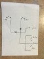
I hope I can discribe all of this correctly. I have a switch (paddle shifter) for shifting up and one for downshifting. Currently, I have a M/T mode on my automatic. I need to tap into this shifter with my paddles. When not upshifting or downshifting the wire I am tapping into reads 0.66VDC, when I upshift it reads 1.0VDC, when I downshift it reads 2.0VDC. I have a 2.45VDC + wire and ground right beside it that I can access. I tried to do a dropping resistor but I cannot get it to work. Does anyone know how I can obtain these specific voltages? I also don’t mind using 12V pos. Here is a crappy sketch of what I am talking about.
 

Attachments

geekoftheweek

Joined Oct 6, 2013
1,429
What transmission are you working with? I've found in my line of work that sometimes PWM signals are used for strange things as a way to detect shorts and bad connections... which will show a voltage, but not give you the whole picture.
 
Last edited:

Thread Starter

Ablues10

Joined Dec 5, 2017
19
What transmission are you working with? I've found in my line of work that sometimes PWM signals are used for strange things as a way to detect shorts and bad connections... which will show a voltage, but not give you the whole picture.
Its a GM 6L50. Car is a 2010 Cadillac CTS. I dont know anything about the electronics of the transmission. I cant even seem to get a 1.0 or 2.0 just to test the idea. The dropping resistor doesnt seem to work. GOing from 12V to 1.0 or 2.0 burns up the resistor but I do see the voltage I need before it burns up.
 

Thread Starter

Ablues10

Joined Dec 5, 2017
19
Wow, Im dumb. Hows this: V in =12V, R1=660ohm 1/4W, R2= 3.3K ohms. Wattage should be around .21W and current is around .018 across the 660?
 

Thread Starter

Ablues10

Joined Dec 5, 2017
19
Ok, so here is my new problem. I have fluctuating voltage, 12VDC to 14.5VDC sometimes 15.0. How do I get consistent output?
 

MrSoftware

Joined Oct 29, 2013
2,273
As @geekoftheweek mentioned, it sounds like it's possible that an analog DC voltage isn't the acutal signal. Can you get a scope on there to make sure you're seeing a DC voltage? You don't want to be sending DC down a line that is expecting something else, like PWM.

If it's PWM then a DC volt meter may show different DC voltage based on the PWM duty cycle.
 

Thread Starter

Ablues10

Joined Dec 5, 2017
19
As @geekoftheweek mentioned, it sounds like it's possible that an analog DC voltage isn't the acutal signal. Can you get a scope on there to make sure you're seeing a DC voltage? You don't want to be sending DC down a line that is expecting something else, like PWM.

If it's PWM then a DC volt meter may show different DC voltage based on the PWM duty cycle.
Well, I dont have a scope but I would like to buy a cheaper one. I know these are by far not the best but out of the 2, any idea which one I should buy?

https://www.amazon.com/Oscilloscope...&qid=1513022266&sr=1-46&keywords=oscilloscope

https://www.amazon.com/kuman-FY2202...&qid=1513022266&sr=1-37&keywords=oscilloscope
 

MrSoftware

Joined Oct 29, 2013
2,273
The second one is a signal generator, it's not what you need.

Some of the comments on the first one say that there is no time or voltage scale on the oscilloscope, just a picture of the wave form with no units. This won't help you much. You might be able to see the wave form, but with no time scale you can't tell if it's really PWM or not, so I don't think this one will help you much either unfortunately.
 

Thread Starter

Ablues10

Joined Dec 5, 2017
19
The second one is a signal generator, it's not what you need.

Some of the comments on the first one say that there is no time or voltage scale on the oscilloscope, just a picture of the wave form with no units. This won't help you much. You might be able to see the wave form, but with no time scale you can't tell if it's really PWM or not, so I don't think this one will help you much either unfortunately.
https://www.amazon.com/Hantek-HT602...&qid=1513025001&sr=1-12&keywords=oscilloscope

How about this one?
 

MrSoftware

Joined Oct 29, 2013
2,273
If you want to bare bones it, then something like this might do the trick:

https://www.amazon.com/Longruner-DSO138-Digital-Oscilloscope-Assembled/dp/B06XZ1VXRV/ref=pd_sbs_328_3?_encoding=UTF8&pd_rd_i=B06XZ1VXRV&pd_rd_r=9RQM610C6CR3R90N4F56&pd_rd_w=RiqwN&pd_rd_wg=G6Exn&psc=1&refRID=9RQM610C6CR3R90N4F56

This might help confirm whether you have PWM or not, but may or may not give enough info to reproduce the PWM, if that's your goal. If it's not PWM, but some protocol like SPI, I2C, CAN, etc.. then a logic analyzer would be more useful if you want to figure out exactly what is being sent. I guess what I'm saying is, a scope may give you more information about what's on the wire, but may not provide enough information to reproduce what's on the wire. Some sort of factory repair manual would help you more than anything. Maybe check in some car specific forums to see if anyone can help with documentation before you go spending money on tools. Unless you just like buying tools (I do!), in which case go for it. ;)
 

Thread Starter

Ablues10

Joined Dec 5, 2017
19
If you want to bare bones it, then something like this might do the trick:

https://www.amazon.com/Longruner-DS...rd_wg=G6Exn&psc=1&refRID=9RQM610C6CR3R90N4F56
This might help confirm whether you have PWM or not, but may or may not give enough info to reproduce the PWM, if that's your goal. If it's not PWM, but some protocol like SPI, I2C, CAN, etc.. then a logic analyzer would be more useful if you want to figure out exactly what is being sent. I guess what I'm saying is, a scope may give you more information about what's on the wire, but may not provide enough information to reproduce what's on the wire. Some sort of factory repair manual would help you more than anything. Maybe check in some car specific forums to see if anyone can help with documentation before you go spending money on tools. Unless you just like buying tools (I do!), in which case go for it. ;)
Ive checked forums and I am going into uncharted territory. I guess most techies dont drive Cadillacs. I will order it and give it a shot. I can use it with other projects I have going on. Ill post results as soon as I get it in the mail. Hopefully before the weekend.
 

geekoftheweek

Joined Oct 6, 2013
1,429
Well, I dont have a scope but I would like to buy a cheaper one. I know these are by far not the best but out of the 2, any idea which one I should buy?

https://www.amazon.com/Oscilloscope...&qid=1513022266&sr=1-46&keywords=oscilloscope

https://www.amazon.com/kuman-FY2202...&qid=1513022266&sr=1-37&keywords=oscilloscope
If you can get a scope I'll be jealous. If you need something to get you by a decent true RMS multimeter with a frequency setting will at least let you know if it's PWM or not. What I work with tends to be around 1,000 to 20,000 Hz if I remember correctly and the duty cycle is what changes to signify different events. I never get to use this knowledge, but it helped understand how it all works in the long run.

Nevermind the meter idea... I checked out the link @MrSoftware put on and I would go that route.
 
Last edited:

geekoftheweek

Joined Oct 6, 2013
1,429
If you want to bare bones it, then something like this might do the trick:

https://www.amazon.com/Longruner-DS...rd_wg=G6Exn&psc=1&refRID=9RQM610C6CR3R90N4F56
This might help confirm whether you have PWM or not, but may or may not give enough info to reproduce the PWM, if that's your goal. If it's not PWM, but some protocol like SPI, I2C, CAN, etc.. then a logic analyzer would be more useful if you want to figure out exactly what is being sent. I guess what I'm saying is, a scope may give you more information about what's on the wire, but may not provide enough information to reproduce what's on the wire. Some sort of factory repair manual would help you more than anything. Maybe check in some car specific forums to see if anyone can help with documentation before you go spending money on tools. Unless you just like buying tools (I do!), in which case go for it. ;)
Thanks for the link. I'm thinking of getting one myself now... it would at least help with a few other projects.

@Ablues10... I found a used shifter on ebay and checked it out. Since it's not a totally electronic shifter (still has a cable) and the sheer number of wires on it (looks like eight or more) I would assume it's either a PWM or even may actually be an analog signal and resistors will do the trick. @MrSoftware made me think for a minute with the SPI, I2C, and CAN talk... luckily probably not part of the puzzle this time.
 
Last edited:

Thread Starter

Ablues10

Joined Dec 5, 2017
19
Upshift is between 2.57 and 2.61vdc
Downshift is 1.45vdc ish
Between shifts is about .96vdc

I didn’t see any freq being generated with the signal wire and ground wire hooked to the probes. With only the signal wire hooked up I got an erratic off the chart signal. I couldn’t get any kind of decent reading. This was at all 3 positions.


52758EC0-60DC-4356-92C1-5569BEBDC863.jpeg2064CC4C-D3F5-4736-8718-46BB9BF4E499.jpeg
 

MrSoftware

Joined Oct 29, 2013
2,273
That second image does look like a nice square voltage step up. If you turn your time base way up (will it support 1s or 2s per division?) then can you catch the entire up-shift or down-shift on screen?

Without the ground attached the readings will be junk.
 

Thread Starter

Ablues10

Joined Dec 5, 2017
19
That second image does look like a nice square voltage step up. If you turn your time base way up (will it support 1s or 2s per division?) then can you catch the entire up-shift or down-shift on screen?

Without the ground attached the readings will be junk.
The second image is when I did the downshift. It goes flat after that.
 
Top