 Facebook
 Google
 GitHub
 Linkedin
Got a situation here that has me pulling the rest of my hair out.
Have a project I designed/prototyped with the mother board on a solderable breadboard using a P82B715, with 33K pull up resistors on my Sx and Sy pins, and 2k on my Lx and Ly pins. My remote sensor was cobbled together with a stub of Cat5 cable connected to a second P82B715, jumper wires, 33K pull up resistors on Sx and Sy, and a Honeywell I2C pressure sensor. No Lx and Ly pull ups on the remote per the DS. Then 50' of cat 5 cable in between.
System worked fine. Looks horrible and is tremendously delicate even after potting the birds nest of wire, but it worked.
So I drew up some PCBs to place the remote components on a daughter board. The circuit is so simple, I decided to go ahead and solder the whole thing together, do the mechanical assembly and pot it all into a condulet. Imagine my disappointment when it didnt work when I went to test it yesterday... Couldnt troubleshoot it because its all potted. But there was a short length of Cat5 going from the daughter board to an IP67 connector that was suspect from the beginning so I figured maybe one of the contacts was bad.
So today I made up a new daughter board once more sensors arrived by FedEx overnight. Soldered it all together, and nope, it still doesn't work. If I plug my basket case prototype sensor back in, it works fine.
Differences between the prototype and the PCB version: 1/8w through hole pull up resistors replaced with 1206s but still 33K. PDIP-8 package in the prototype replaced with SOIC. Wurth 615008140421 replaces a stub of Cat5 soldered directly to chip. Same part number Honeywell sensor.
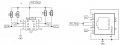
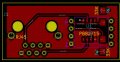
This was my first attempt at doing a PCB layout. I guess first I am wondering if there is anything that stands out that I did wrong. Schematics attached.
When the circuit is powered up, I have 5V at pin 8 of the P82B and pin 2 of the sensor as well as on each side of my pull ups. I have ground at pin 4 of the PB82 and pin 1 of the sensor. I have continuity between pin 3 of the P82 and pin 3 of the sensor. I have continuity between pin 6 of the P82 and pin 4 of the sensor. I have continuity between pin 2 of the P82 on the mother board and pin 2 of the P82 on the daughter board, and likewise the same for pin 7.
I am lost. Would changing my pull ups on the daughter board change anything, even though its the same as my basket case version.
PS, if you look at the PCB layout, the top copper is red, bottom copper is green, and the sensor is mounted on the BACK of the board which is why the pinout is backwards.
THANKS IN ADVANCE!
Have a project I designed/prototyped with the mother board on a solderable breadboard using a P82B715, with 33K pull up resistors on my Sx and Sy pins, and 2k on my Lx and Ly pins. My remote sensor was cobbled together with a stub of Cat5 cable connected to a second P82B715, jumper wires, 33K pull up resistors on Sx and Sy, and a Honeywell I2C pressure sensor. No Lx and Ly pull ups on the remote per the DS. Then 50' of cat 5 cable in between.
System worked fine. Looks horrible and is tremendously delicate even after potting the birds nest of wire, but it worked.
So I drew up some PCBs to place the remote components on a daughter board. The circuit is so simple, I decided to go ahead and solder the whole thing together, do the mechanical assembly and pot it all into a condulet. Imagine my disappointment when it didnt work when I went to test it yesterday... Couldnt troubleshoot it because its all potted. But there was a short length of Cat5 going from the daughter board to an IP67 connector that was suspect from the beginning so I figured maybe one of the contacts was bad.
So today I made up a new daughter board once more sensors arrived by FedEx overnight. Soldered it all together, and nope, it still doesn't work. If I plug my basket case prototype sensor back in, it works fine.
Differences between the prototype and the PCB version: 1/8w through hole pull up resistors replaced with 1206s but still 33K. PDIP-8 package in the prototype replaced with SOIC. Wurth 615008140421 replaces a stub of Cat5 soldered directly to chip. Same part number Honeywell sensor.
This was my first attempt at doing a PCB layout. I guess first I am wondering if there is anything that stands out that I did wrong. Schematics attached.
When the circuit is powered up, I have 5V at pin 8 of the P82B and pin 2 of the sensor as well as on each side of my pull ups. I have ground at pin 4 of the PB82 and pin 1 of the sensor. I have continuity between pin 3 of the P82 and pin 3 of the sensor. I have continuity between pin 6 of the P82 and pin 4 of the sensor. I have continuity between pin 2 of the P82 on the mother board and pin 2 of the P82 on the daughter board, and likewise the same for pin 7.
I am lost. Would changing my pull ups on the daughter board change anything, even though its the same as my basket case version.
PS, if you look at the PCB layout, the top copper is red, bottom copper is green, and the sensor is mounted on the BACK of the board which is why the pinout is backwards.
THANKS IN ADVANCE!
Attachments
-
 38 KB Views: 14
 -
 51.6 KB Views: 13
 -
 128.6 KB Views: 14
 -
 117.9 KB Views: 13
 -
890.8 KB Views: 3
-
 60.3 KB Views: 12


