Overlapped PWM signals

Thread Starter

Mohaimen_97

Joined May 18, 2023
6
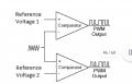
Hey , I need any reference ( online, books or papers) for PWM mudulator that generate two overlapped PWM signals using comparators and triangular wave as a carrier , the overlapped time is defined as :
(D-0.5)*T , the general circuit diagram is shown in the picture
Please help , I need any reference ASAP
 

Attachments

Thread Starter

Mohaimen_97

Joined May 18, 2023
6
What are the limits on D?
What happens if D<0.5?
Push-pull normally requires complementary signals, i.e non-overlapped (as Crutschow mentions). Overlap would result in undesirable shoot-through.
The circuit I'm talking about is current fed converter where the inductor is in the input side and not the normal voltage fed topology, the overlapping is a must because otherwise the inductor voltage spikes very high and the switches fail.
 

Ian0

Joined Aug 7, 2020
13,132
What are the limits on D?
What happens if D<0.5?
Push-pull normally requires complementary signals, i.e non-overlapped (as Crutschow mentions). Overlap would result in undesirable shoot-through.
A current-fed converter does require PWM signals that overlap. There is no shoot-through as there is a choke in series.
I've not made one, but from what I recall from the application note, the PWM comes from a normal single-output controller.
It is then divided by two with a 74HC74, and the 74HC74 Q and notQ outputs are OR'd with the PWM to give the two overlapping signals to drive the FETs.
 

Thread Starter

Mohaimen_97

Joined May 18, 2023
6
A current-fed converter does require PWM signals that overlap. There is no shoot-through as there is a choke in series.
I've not made one, but from what I recall from the application note, the PWM comes from a normal single-output controller.
It is then divided by two with a 74HC74, and the 74HC74 Q and notQ outputs are OR'd with the PWM to give the two overlapping signals to drive the FETs.
Exactly , I remember seeing the design somewhere online (probably IEEE paper or master thesis) as a part of a bigger subject ,and that's where I got the idea but now I can't find it anywhere
 

Ian0

Joined Aug 7, 2020
13,132
Exactly , I remember seeing the design somewhere online (probably IEEE paper or master thesis) as a part of a bigger subject ,and that's where I got the idea but now I can't find it anywhere
It's in an old Unitrode databook. They made an IC to do it - I can't remember the number, but it will start "UC".
 

LowQCab

Joined Nov 6, 2012
5,101
When a particular design has faded into obscurity,
it's usually because it's either ..........

not as efficient as newer designs,
and/or,
it may be more expensive to produce than newer designs,
and/or,
it may not be as reliable as newer designs for some odd reason.

Nostalgia-value not withstanding,
the marketplace doesn't make very many significant "accidental" omissions.

There is probably a more prolific design/topology
that will completely fulfill the requirements of this project.
.
.
.
 
Top