Oscillator - varactor diode... inductance meter.. Common base colpitts understanding

Thread Starter

Zeeus

Joined Apr 17, 2019
616
@Audioguru again : I think you can answer my first question

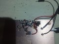
Please look first image :

In normal common base colpitts : there is a capacitor from the emitter side to ground and from emitter to collector : here no emitter capacitor : in calculating frequency : the total capacitance in the image circuit will be (0-40) + 4.7 pf correct?
Can't understand it : use to think the emitter should be grounded or with little degeneration. Please someone explain everything : don't understand it

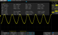
In the 2nd image : excluding the 0-25pf, the total capacitance is 43 in series with 140 correct? Used to think the 140pf was like a low pass filter but now guess it is part of the colpitts

If correct in the last sentence then the frequency is about 51Mhz but in the book it is meant to be 88-108 Mhz

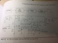
What then is the use for the varactor diode in the last 2 images ? where should it be placed? at collector? why? what does it do?

Thanks thanks, thanks and................. Thanks

Also, some months ago : found an inductance meter on aliexpress than could measure down to nH (someone posted image on measuring air inductor) : now can afford it but can't find it anymore... Can someone asssist please?

Also, looking at the 3rd image : In any calculation , the 100 ohms and 1k are in parallel yeah?
 

Attachments

Danko

Joined Nov 22, 2017
1,829
3 parallel coils 0.1u each.
Then inductance is 0.1/3 = 0.03(3)u.
So frequency with cap 43pF is 133.6MHz.

1k and 100Ω are in series for voltage from divider 16pF, 16pF.

Varactor connected in parallel with tank.
Varactor changes its capacitance in tact with audio signal
and slightly changes frequency.
Modulation.

Capacitor from emitter to ground decreases positive feedback (if needed).
Without this capacitor positive feedback is maximal.
 
Last edited:

Thread Starter

Zeeus

Joined Apr 17, 2019
616
3 parallel coils 0.1u each.
Then inductance is 0.1/3 = 0.03(3).
So frequency with cap 43pF is 133.6MHz.

1k and 100Ω are in series for voltage from divider 16pF, 16pF.

Varactor connected in parallel with tank.
Varactor changes its capacitance in tact with audio signal
and slightly changes frequency.
Modulation.

Capacitor from emitter to ground decreases positive feedback (if needed).
Without this capacitor positive feedback is maximal.
I am a fool : I added the inductance

Thanks

really, 1k and 100 are in series?????
"

Capacitor from emitter to ground decreases positive feedback (if needed).
Without this capacitor positive feedback is maximal."

Please elaborate...Thanks
 

Danko

Joined Nov 22, 2017
1,829
1st divider - C1 in series with C2.
2nd divider - R1 in series with R2.
1575609469800.png
EDIT:
Emitter is INPUT! ;)
 
Last edited:

Danko

Joined Nov 22, 2017
1,829
Same as in first circuit - changes frequency of tank
under voltage (tune voltage).
L2 is choke for HF and is like piece of wire for DC tune voltage.
EDIT:
Resistor 510Ω decreases Q of L2 for eliminating parasitic oscillations,
capacitor .001u protect tune voltage source from HF.
 
Last edited:

Thread Starter

Zeeus

Joined Apr 17, 2019
616
Wish can get help to make my 60mhz work : made 1Mhz, 30Mhz

60Mhz not working : still doing common base : want to get right before advancing

For 1st two oscillators : noticed that the base emitter voltage is alot less than .7...if it is .7 then no oscillation
 
Last edited:

Thread Starter

Zeeus

Joined Apr 17, 2019
616
Use no wires, shortest leads only.
For example - see picture.
THink yours is working because you removed the emitter to ground capacitor : but need this capacitor to calculate output amplitude..dunno how to calculate without it

Think I know what problem is :)..Want to learn crystals but this slowing TS..Also, did not use that green cap at first..Anyways, must get 60Mhz on scope

btw, thanks @bertus
 

Attachments

Last edited:

Thread Starter

Zeeus

Joined Apr 17, 2019
616
As was about "giving up" to call it a night : God decided to reward my effort :)

Confused : Used the scope probe on *10 and on the oscilloscope as *10 and that's the reading : about 5v

But if I use *1 on probe and oscilloscope the reading is about 600mv (can say 500mv)

Please what's going on?...The signal is 500mv correct? or the 5v?

Also, this is confusing...Voltage divider is 18k and about 12k to about 8v...expecting 4.8v on the base (2n3866) but it is about 2v lol

100Mhz loading.........

Please someone assist. Thanks
 

Attachments

Danko

Joined Nov 22, 2017
1,829
Congratulations. Good job!

x1 probe has about 8 MHz bandwidth itself.
See this post.
Voltage divider: 18k in series with diode Base-Emitter.
Then voltage on Base is 0.7V.
But, with emitter resistor, voltage on base is 0.7V + I_e * R_e.
And emitter current is partially reversed (current from feedback).
This reversed current decreases Base-Ground voltage.
Try to see these currents and voltages in LTSpice simulation.
 
Last edited:

Thread Starter

Zeeus

Joined Apr 17, 2019
616
Congratulations. Good job!
But, with emitter resistor, voltage on base is 0.7V + I_e * R_e.
And emitter current is partially reversed (current from feedback).
This reversed current decreases Base-Ground voltage.
lol no..till get 100Mhz..will try at home

Thanks for the info
 
Last edited:

Thread Starter

Zeeus

Joined Apr 17, 2019
616
Congratulations. Good job!

x1 probe has about 8 MHz bandwidth itself.
See this post.
Hmm..did not understand ..will try again later : really want understanding

Trying to get 100Mhz..got 75Mhz :( Lack of precision not fun

94Mhz :)
Now Ts can do what every noob like him tries to do lol : simple transmitter..add buffer and antenna
But the great ocean of truth still lays undiscovered before Ts

Please explain your link in last post..Also, in the varactor diode in #5..what's L2 for?

Thanks Danko

Also, a little bit weird : in #5..emitter current is about 1mA and it is for high frequency but discovered HF oscillators not working for me without "high" current like 20mA : maybe it's the varactor diode?

Anyways, maybe later experience teaches Ts another lesson
 

Attachments

Last edited:

Danko

Joined Nov 22, 2017
1,829
Hmm..did not understand ..will try again later : really want understanding
It is my misunderstanding.
1. Set the Probe option attenuation in the channel menu to 10X.
Set the switch to 10X on the probe and connect the probe to channel 1 on the oscilloscope.

SDS1000DL user manual, page 8.
1575737864123.png
Always use this setting, except cases, when you work in mV range,
low frequency signals, where you have to use 1X probe.
1575742005576.png
SDS1000DL user manual, page 8.
Please explain your link in last post..
That link is exactly about 1X probe bandwidth limit.
Also, in the varactor diode in #5..what's L2 for?
L2 (1...2mH) has very big impedance at 100MHz frequency and
prevents HF leakage to tune voltage circuit.
Also, a little bit weird : in #5..emitter current is about 1mA and it is for high frequency
but discovered HF oscillators not working for me without "high" current like 20mA :
maybe it's the varactor diode?
Varactor diode is just part of tank capacitance and do not affect on emitter current.
Emitter current depends on emitter resistor value and Base-Ground voltage.
 
Top