Oscillator help

Thread Starter

Saviour Muscat

Joined Sep 19, 2014
187
Dear members,

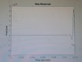
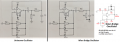
I am trying to answer coursework given to do at home regarding a sinusoidal oscillator as shown in the photo attached(fig1). I did some find out on books and the internet and I found nothing similar, unfortunately. I deduced at the output of the opamp has an RC bandpass filter and is also connected to the positive feedback of the opamp.
My first difficulty, is it need any modifications of this circuit(fig1) to work?
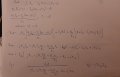
Second, I did some derivation(fig2,3,4) to find the cutoff frequency and also the loop gain, but I am not 100% sure of my work, could someone correct or point out the mistakes did?

Please could someone guide me the way forward please.


Thanks for your kind attention,
Saviour
 

Attachments

RBR1317

Joined Nov 13, 2010
713
It would seem that this is a problem that requires application of the Barkhausen stability criterion. And you may have done this, but it is not obvious from the work shown. Also, Fig. 4 shows, "At resonance j=0" but it is also true that "j" always equals "j". ???
 

Thread Starter

Saviour Muscat

Joined Sep 19, 2014
187
Thanks, RBR1317,

Yes, you are right, I mean, at resonance the imaginary component is 0 and only the real part(horizontal component) is considered(terms with a coefficient of "j"), thus at resonance( for oscillations phase shift should be equal 0deg or 360deg) the reactance of the capacitor and the resistance should cancel each other. jXC1/R3 + R4/jXC2 = 0, C1=C2=C and R3=R4=R we need only one cut off frequency therefore XC=R


To find B At the resonant frequency(img terms equal to 0) -XC1/XC2 + XC1*R4/XC2*R3 -1 ,
C1=C2 and R3=R4
-1+1-1
B=-1
For condition for oscillations AB=1,
A*-1=1,
A=-1,
(before I did a mistake I am confused)Non inverting amplifier Rf/Rin + 1 =-1..???????

Thanks for your aid,
Saviour
 
Last edited:

RBR1317

Joined Nov 13, 2010
713
While I have not tried solving this problem, what I would try first is solving it as an op-amp problem. Don't calculate Vout; assume that there is a Vout then calculate the voltage at the (+) and (-) op-amp inputs. Set V(+)=V(-) and see what you get. Then look at the phase shift from Vout to V(+) and Vout to V(-).
(Meanwhile...Doom Eternal calls)
 

MrAl

Joined Jun 17, 2014
11,388
Hi,

Do you know for sure if this circuit actually oscillates?
I ask because there are certain criteria for oscillation to occur and i am not sure this circuit meets that.
I can check for you later but you should try to figure it out for yourself.
One way you can tell is if the transfer function is entirely real then it could not oscillate because it will always be overdamped. Overdamped means there are no sinusoidal terms in the output response just exponentials alone or sinusoidal terms with exponenttials that cause the output to die out after some time.
Underdamped means that there are sinusoidal terms in the output response but they increase with time thus saturating the system.
The key is to get the gain right so that the response is directly in between these two.

{LATER]
It does look like it can oscillate with just one choice of gain. However, the response is usually set slightly underdamped so that any small change in gain will not stop the oscillations and the diodes keep the gain at the right place by clipping the output if it goes too high.
 
Last edited:

Thread Starter

Saviour Muscat

Joined Sep 19, 2014
187
Dear RBR1317,
Thanks for your help
While I have not tried solving this problem, what I would try first is solving it as an op-amp problem. Don't calculate Vout; assume that there is a Vout then calculate the voltage at the (+) and (-) op-amp inputs. Set V(+)=V(-)
I tried to do derivation but I am stuck there!! please refer to scanned working Fig5 and Fig6. please suggest the way forward!!

Dear MrAl,
Also thank you for your help,
loop gain B*A=1 , I found B where R=10Kand C=100nF, B=10000s/(s^2-10000s+100000000)
I plotted(B) the step input of the transfer function fig7 of the oscillator that seems underdamped(uncontrolled), but how can I deduce the gain such that we will have sustained oscillations?

Thankyou again,
Saviour
 

Attachments

MrAl

Joined Jun 17, 2014
11,388
Dear RBR1317,
Thanks for your help

I tried to do derivation but I am stuck there!! please refer to scanned working Fig5 and Fig6. please suggest the way forward!!

Dear MrAl,
Also thank you for your help,
loop gain B*A=1 , I found B where R=10Kand C=100nF, B=10000s/(s^2-10000s+100000000)
I plotted(B) the step input of the transfer function fig7 of the oscillator that seems underdamped(uncontrolled), but how can I deduce the gain such that we will have sustained oscillations?

Thankyou again,
Saviour

Hello,

When you say uncontrolled, what exactly do you mean?
Do you mean that the oscillations ramp up and up getting larger and larger?
If that's the case, then the gain is not set right yet.

To compute what gain is required, you have a couple options.
1. Use an inverse laplace transform on the transfer function and simply look at the exponential part of the exponential term(s). Choose gain G so that any exponentials disappear leaving only the sinusoidal term(s) (theoretical case) and for the practical case choose gain G such that the sinusoid ramps up slowly.
2. Use a root locus to find out when the roots cross the jw axis, choosing the gain that allows only a sinusoidal response for the theoretical example (and that means the roots like on the jw axis) and for the practical example find the gain that places the root just to the right of the jw axis.

But did you find the transfer function? You need that for both of these techniques, then it gets really simple.

I used #1 above to verify that the circuit is capable of oscillations. I did not do #2 yet.
The reason i quote the theoretical and the practical is because for the theoretical case the diodes are not required because the gain G never changes, but for the practical case we cant be sure the gain will stay the same so we use a slightly different gain and allow the diodes to automatically adjust the 'gain' in order to sustain oscillations.
 

MrAl

Joined Jun 17, 2014
11,388
Hello again,

Here is a root locus plot of the system as the gain varies..
Note that the graph line crosses zero on the x axis (the real axis) and at that point w=1 or -1.
At that point there is a particular value of the gain that causes that. That is the value you are looking for. You can always tweek it a little for the practical circuit.

The plot is found by manipulating the transfer function a little and then finding the roots as the gain is varied. Eventually a gain value is reached where the graph line crosses the 0 on the x axis.

I dont want to state the value of the gain just yet, but this gives you some idea of how this could be found. The root locus tells you even more about the system so it's good to learn how to do it.
You could also find the roots of the characteristic equation with s=jw and you could get w from the transfer function, so you could just solve for one value if you like.

When you use the Inverse Laplace Transform you can get a good view of what is happening too. The basic transfer function has at least one exponential e^-at and one or two sinusoidal terms. In order to sustain oscillations, the exponential value 'a' must be zero so that e^-at turns into a constant "1" and that leaves a pure sinusoid. The form looks like this:
e^(-a*t)*(A*sin(w*t)+B*cos(w*t))
or that with just one of the trig terms.
So when a=0 we get:
A*sin(w*t)+B*cos(w*t)
and that is the pure sinusoid response we are looking for.

Later, you can make 'a' slightly negative so that the wave is a sinusoid with amplitude rising slowly in order to meet the requirements of a practical circuit.

It's very good to learn both of these approaches.
Just to note, the required gain is not 1.
In the graphic, the small white dot on the far left of the graph line is when the gain is equal to zero. The graph then progresses from left to right as the gain is gradually increased.
OscillatorRootLocus-01.png
 
Last edited:

LvW

Joined Jun 13, 2013
1,752
S. Muscat - the shown circuit has EXACTLY the same properties as the well-known WIEN-oscillator.
That means: For C1=C2=C and R3=R4=R the oscillation frequency is wo=1/RC and the required positive gain (determined by the resistors in the negative feedback loop) must be G=+3 (theoretically).
In practice (safe start of oscillation with amplitude limitation) the gain must be slightlx larger than 3 and the diodes reduce the loop gain back to unity for rising amplitudes. Therefore, make the ratio R1/R2 slightly larger than "2".
The circuit will safely start to oscillate.

Comment: Your method for calculation is rather involved. It is better to split the whole process into two parts:
* It is easy to find the transfer function of the second-order RC bandpass in the positive feedback loop. Hint: From the beginning, use equal R and equal C. Then, you will see that at w=1/RC the transfer function is real (resonance) an the magnitude is 1/3.
* Therefore, for a loop gain of unity, the required opamp gain is (ideally) G=3. Hence, we have R1/R2=2.

Hint: In reality, the oscillator will start due to the switch-on transient of the power supplies. For simulation, you need another kick-off puls, for example: Give one of the capacitors an initial condition (some millivolts are sufficent)
 
Last edited:

MrAl

Joined Jun 17, 2014
11,388
S. Muscat - the shown circuit has EXACTLY the same properties as the well-known WIEN-oscillator.
That means: For C1=C2=C and R3=R4=R the oscillation frequency is wo=1/RC and the required positive gain (determined by the resistors in the negative feedback loop) must be G=+3 (theoretically).
In practice (safe start of oscillation with amplitude limitation) the gain must be slightlx larger than 3 and the diodes reduce the loop gain back to unity for rising amplitudes. Therefore, make the ratio R1/R2 slightly larger than "2".
The circuit will safely start to oscillate.

Comment: Your method for calculation is rather involved. It is better to split the whole process into two parts:
* It is easy to find the transfer function of the second-order RC bandpass in the positive feedback loop. Hint: From the beginning, use equal R and equal C. Then, you will see that at w=1/RC the transfer function is real (resonance) an the magnitude is 1/3.
* Therefore, for a loop gain of unity, the required opamp gain is (ideally) G=3. Hence, we have R1/R2=2.

Hint: In reality, the oscillator will start due to the switch-on transient of the power supplies. For simulation, you need another kick-off puls, for example: Give one of the capacitors an initial condition (some millivolts are sufficent)
Hello,

We are not supposed to give out the answer in the Homework section. Read one of the sticky's the first one titled:
"Remember that this is Homework Help and not Homework Done For You "

However there is a light in the clouds here...
That is, he still doesnt know if he should set the inverting gain to 3 or the non inverting gain to 3. If you dont mention that here he will have to figure it out for himself, which is good.
The other light in the clouds is that you could be wrong altogether so he will have to figure that out too.
 

Thread Starter

Saviour Muscat

Joined Sep 19, 2014
187
Dear MrAL,

I am a little bit confused, could you explain more root locus applied in oscillator please because I can't figure it out how can apply to the transfer function B=10000s/(s^2-10000s+100000000) so I can deduce the gain of the non-inverting amplifier. Further than that, I am might be wrong the "10000s" term should be small enough to have oscillations only so we have Imaginary parts only?

Regarding Laplace Transform I found Table fig8 the last one at the bottom ie (sA+C)/(s^2+2as+c) If understood well, "a" need to be small so the exponential term could be 1, so it will remain sinusoidal terms only. I will try to put a=0.01 Is it good?? If yes how can I find the gain of the opamp, please?

Thank you for your kind help.

Dear LvW,
Also thank you
I tried to derive 1/3 with no result, please could you be patient to show a segment of the working so I could be capable to get the gain of 3?

Again thank you,
Saviour
 

Attachments

MrAl

Joined Jun 17, 2014
11,388
Dear MrAL,

I am a little bit confused, could you explain more root locus applied in oscillator please because I can't figure it out how can apply to the transfer function B=10000s/(s^2-10000s+100000000) so I can deduce the gain of the non-inverting amplifier. Further than that, I am might be wrong the "10000s" term should be small enough to have oscillations only so we have Imaginary parts only?

Regarding Laplace Transform I found Table fig8 the last one at the bottom ie (sA+C)/(s^2+2as+c) If understood well, "a" need to be small so the exponential term could be 1, so it will remain sinusoidal terms only. I will try to put a=0.01 Is it good?? If yes how can I find the gain of the opamp, please?

Thank you for your kind help.

Dear LvW,
Also thank you
I tried to derive 1/3 with no result, please could you be patient to show a segment of the working so I could be capable to get the gain of 3?

Again thank you,
Saviour
Hi again,

Yes i can show part of the work and i think i should because your function does not look right because it has no gain factor like "G" or "K" in it, and in order to plot a root locus or even solve for one point you must have gotten a function which had the gain factor in it. Let me see if i can show part of this...

First, we have the R's and C's at the output of the amplifier. I assume you know how to calculate the transfer function of just that section from the output of the op amp to the input of the op amp non inverting terminal.
Let's call that function RC(s) as it is a function of s, or just RCs for short.
So you have a gain K and the output goes to the input of RCs, then the output of the RCs goes into the non inverting terminal which means a positive value for K.
You know the formula for the root locus is:
1-G(s)*H(s)=0
where we subtract because the gain is positvie and
where H(s) is the feedback factor and G(s) is the forward factor.
This means that G(s) is the gain K, and H(s) is the RCs function.
Putting that into the formula we get:
1-K*RCs=0

Since RCs has numerator and denominator, we can say that:
Ns/Ds=RCs

then we have:
1-K*Ns/Ds=0

factoring we get:
(Ds-Ns*K)/Ds=0

multiply by Ds we get:
Ds-Ns*K=0

Now this will look like some function of s like:
2*s^2+6*s+4-K*s=0 {note this is an arbitrary function not the one you get here but it will be similar}

and so solve that for s and you get a function of K alone
s=f(K)
Now try to solve that equation for when s is imaginary only.
This will look like this:
w*j

but it will not have a real part like this:
w*j+1

or even like this:
w*j+0.00001

So when you find that value of K that results in a purely imaginary value for s you have the value of K the gain.
This step is much much easier if you set R=1 and C=1, because those values as well as other values will result in the same gain.
You must then convert that gain into a negative gain so you can set the two gain resistors.

You can also try setting s=jw and solving for the real part set equal to zero:
2*jw^2+6*jw+4-K*jw=0
realpart(2*jw^2+6*jw+4-K*jw)=0

Now when you solve the result for that you have the value of w then you can solve for K.
For that example we have:
realpart(-j*w*K-2*w^2+6*j*w+4)=0
4-2*w^2=0
w=sqrt(2)

Now insert that into the same equation we get:
3*sqrt(8)*j-sqrt(2)*j*K=0
solving for K we get:
K=6

See if that helps.

Just remember when you deal with a positive gain you subtract 1-G*H=0 and when you deal with a negative gain you add 1+G*H=0.
Also, remember that when you solve this you get the gain as if it was as non inverting amplifier.
I have confidence that you can solve for the gain required to set the two gain resistors, just remember the way the gain changes from inverting to non inverting.

To plot a root locus you vary the gain K and solve for the roots repeatedly or look up the manual way of plotting it.

We can look at the time domain solution next.
 
Last edited:

LvW

Joined Jun 13, 2013
1,752
I have never seen your circuit before. Maybe it is a Wien Bridge oscillator drawn wrongly?
Hi again,
In principle, there ar three basic alternatives for constructing a passive second-order RC bandpass to be used in a simple baandpass oscillator - and one of these 3 types is shown in the given circuit (CR-RC bandpass) .
The other two types are RC-CR and the WIEN type.
Note that ALL three have the same transfer function and, hence, require the same active block to get an oscillator.
 

LvW

Joined Jun 13, 2013
1,752
Dear LvW,
Also thank you
I tried to derive 1/3 with no result, please could you be patient to show a segment of the working so I could be capable to get the gain of 3?
I think, it is not a very involved task to find the transfer function of the RC bandpass in the feedback loop.
Are you aware of the oscillation condition?
It must be your goal to find the frequency where the phase shift of this bandpass is zero. That means: The transfer function (which is complex) must be REAL for this frequency (set the imaginary parts to zero).
That is the way to find the oscillation frequency as well as the damping of the bandpass which must be compensated by a suitable gain within the loop.

Summary: Starting with the well-known oscillation condition (Barkhausen) and knowing the transfer function (s-domain) of the passive RC-bandpass it is really a simple task to understand and design the given circuit for producing self-sustained oscillations.
 
Last edited:

Thread Starter

Saviour Muscat

Joined Sep 19, 2014
187
Dear MrAL&LvW,

Sorry for the late reply because I was at work

Thank you I have done the derivation of the transfer function, which resulted (R^2 C^2 s^2+3RCs+1)/ (2RCs+1)kindly confirm the answer.
then you said 1-K* (R^2 C^2 s^2+3RCs+1)/(2RCs+1)=0(for positive feedback)
S^2(KR^2C^2)+s(3KRC-2RC)+(K-1)=0 to solve for s using the quadratic formula s=(-b+-Root(b^2-4ac))/2a
I am stuck here because the solution doesn't make sense
guide me the next step, please

TY
SM
 

MrAl

Joined Jun 17, 2014
11,388
Dear MrAL&LvW,

Sorry for the late reply because I was at work

Thank you I have done the derivation of the transfer function, which resulted (R^2 C^2 s^2+3RCs+1)/ (2RCs+1)kindly confirm the answer.
then you said 1-K* (R^2 C^2 s^2+3RCs+1)/(2RCs+1)=0(for positive feedback)
S^2(KR^2C^2)+s(3KRC-2RC)+(K-1)=0 to solve for s using the quadratic formula s=(-b+-Root(b^2-4ac))/2a
I am stuck here because the solution doesn't make sense
guide me the next step, please

TY
SM
Hello again,

I think your main problem here is that you are not calculating the transfer function properly, or even the 1+G*H function. You need to go back to basic circuit analysis to do the two RC network You should concentrate on getting that right before you move on to the feedback and roots.

See a transfer function for something like this will either have s^2 in both the numerator and denominator or just in the denominator, but never have s^2 in the numerator and just 's' in the denominator (highest powers of s that is). So go back to the two RC network and see if you can get that right.

There are a number of ways to do that:
Forward Thevenin/Norton,
Backwords-forward impedancs,
straight up Nodal Analysis,
and other methods.

Nodal Analysis is pretty good because it's a very orderly process with a sub procedure repeated for each unknown node.

Also, make sure you have the right circuit as shown in Figure 2 of the attachment.
Figure 3 is the circuit you should start with, compute the transfer function of that from Vin to Vout.

The resulting transfer function for the two RC network alone will have this form:
Vout/Vin=(s*A1)/(s^2*B2+s*B1+B0)
where A1, B2, B1, B0 are all constants not equal to zero and not negative.
 

Attachments

Last edited:
Top