Oscillator help

LvW

Joined Jun 13, 2013
1,752
Thank you I have done the derivation of the transfer function, which resulted (R^2 C^2 s^2+3RCs+1)/ (2RCs+1)kindly confirm the answer.
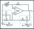
Sorry - no, it is not correct. It must have the form as mentioned by MrAl in his answer #18.
There you can see that (with s=jw) the numerator is imaginary. Hence, the whole function will be real if he denominator is also purely imaginary (real part=0). It is a rather simple calculation.

Hint: After inspecting the passive RC circuit - which output voltage do you expect at very low frequencies (down to w=0)?
Compare this with your function for s=jw=0.
 
Last edited:

MrAl

Joined Jun 17, 2014
11,396
Hello,

Just a small note here...

I went over both circuits that had been shown in this thread, and both double RC networks result in the same transfer function. That explains why the two circuits will work with the same gain value K.
It appears that even if the two resistors are of different values and the two caps are of different values the two RC networks provide the same transfer function. That's interesting i think and now i am wondering if there is some generalization for networks like this and i might look into that.
 

RBR1317

Joined Nov 13, 2010
713
I tried to do derivation but I am stuck there!!
To find the oscillation frequency just look at the feedback path from the op-amp output to the positive input. Write the node equations for the circuit and solve for V(+) given Vo, then solve for the frequency at which there is zero phase shift. As an example I found a circuit for a Wien oscillator which is similar and analyzed that in two different ways - first using Xc to represent the capacitive reactance, and second using 1/(jωC). The suspicion is that using Xc will lead to a problematic result.

So after entering the node equation into Maple and solving for the voltage at the positive input to the op-amp, the solution for V(+) with Xc, expression (2), leaves one wondering where to go next. But the solution for V(+) with 1/(jωC), expression (4), makes it obvious that the zero-phase oscillation frequency is given when C1∙C2∙R1∙R2∙ω^2 = 1.
 

Attachments

Thread Starter

Saviour Muscat

Joined Sep 19, 2014
187
Dear all,
Thanks for all help and understanding,
I did mesh analysis and Kirchoff's and got two identical answers ie Transfer function of
Vout/Vin= SCR/((SCR)^2+3SCR+1)

Just correct the answer if is it wrong
1-K(SCR/((SCR)^2+3SCR+1))=0
(SCR)^2+3SCR+1-KSCR=0
put s=jw
-(wCR)^2+3jCR+1-KjwCR=0
C=R=1
real-w^2+1=0
w=-+1
img -K+3=0
K=3

Many Thanks
SM
 

MrAl

Joined Jun 17, 2014
11,396
Dear all,
Thanks for all help and understanding,
I did mesh analysis and Kirchoff's and got two identical answers ie Transfer function of
Vout/Vin= SCR/((SCR)^2+3SCR+1)

Just correct the answer if is it wrong
1-K(SCR/((SCR)^2+3SCR+1))=0
(SCR)^2+3SCR+1-KSCR=0
put s=jw
-(wCR)^2+3jCR+1-KjwCR=0
C=R=1
real-w^2+1=0
w=-+1
img -K+3=0
K=3

Many Thanks
SM
Hey you got it !!! Great job !
:)

Oh but one more step. You need to convert that gain into a non inverting gain so you can set the two gain resistors. This should be easy for you i know you know how to do it.
 

Thread Starter

Saviour Muscat

Joined Sep 19, 2014
187
Million thanks to MrAl, LvW, RBR1317 and Audioguru again,
My difficulties are sorted for now and I will continue working my course work, hope without difficulties.
Good Day to all,
Saviour
 

Thread Starter

Saviour Muscat

Joined Sep 19, 2014
187
Hello members,
I am trying to implement an analog multiplier of two identical sinewaves(frequency doubler) using opamps ua741. I tried it several times on Orcad and the output displays nothing. Kindly can someone suggest any modifications so the circuit can work please? Please find tentative circuit fig 9 and fig10 attached.
TY
Saviour
 

Attachments

Audioguru again

Joined Oct 21, 2019
6,674
You are inverting and rectifying two identical signals. Instead you need to make an active full-wave rectifier.
Why are you using the old 741 opamp that was designed 52 years ago?
Here is a precision full-wave rectifier circuit:
 

Attachments

MrAl

Joined Jun 17, 2014
11,396
You are inverting and rectifying two identical signals. Instead you need to make an active full-wave rectifier.
Why are you using the old 741 opamp that was designed 52 years ago?
Here is a precision full-wave rectifier circuit:
Isnt his circuit an actual analog multiplier connected as a squaring circuit?
 

MrAl

Joined Jun 17, 2014
11,396
Not with his antique 741 opamp. He didn't say he wanted a squared output.
Ha Ha...the good ol' 741 from the dark ages.

sin(w*t)^2=1/2-cos(2*w*t)/2

we start with frequency w, square it, we end up with 2 times the frequency 2*w.
A side effect is reduced amplitude and a DC offset. So squaring does what he wants after removing the DC component.

Of course the circuit has to function properly which i did not check yet.
It looks like it will only work for positive inputs so it is not four quadrant.
 
Last edited:

Thread Starter

Saviour Muscat

Joined Sep 19, 2014
187
Hello MrAL and Audioguru,
I attempt to answer coursework question Fig11 which says I need to use analog multiplier by driving it using the oscillator done before. I found on a book where Log and Anti Log implemented by two diodes in parallel opposite to each other as seen in fig12 so as it can be used during positive and negative half cycles of the input signal. please find the output signals of the attempt circuit fig13.
Thanks,
Saviour
 

Attachments

LvW

Joined Jun 13, 2013
1,752
Saviour Muscat - do you know that you can use a differential amplifier (with a transistor in the common emitter path) for multiplying two signals?
I would not propose the log-domain for such a purpose...
Or - if you like - you also can use an OTA.
 

Thread Starter

Saviour Muscat

Joined Sep 19, 2014
187
Dear LvW,
Thank you for your reply,
do you know that you can use a differential amplifier (with a transistor in the common emitter path) for multiplying two signals?
Kindly can you elaborate more please( eg giving a circuit sample opamp based, an operating explanation and mathematical derivation or article/book).
Thank you to all,
SM
 

LvW

Joined Jun 13, 2013
1,752
Dear LvW,
Thank you for your reply,

Kindly can you elaborate more please( eg giving a circuit sample opamp based, an operating explanation and mathematical derivation or article/book).
Thank you to all,
SM
The answer is simple: The gain of a differential amplifier is proportional to the transconductance gm of the main transistors (Q1 and Q2). And the transconductance gm is determined by the quiescent emitter current IE. With a 3rd transistor Q3 in the emitter path, this current IE can be varied with a (modulating) signal at the base of Q3. This means: Multiplication.
Drawback of this simple solution: The signals must be pretty small (<< 0.7V) and the output contains a dc portion.
 
Last edited:

Thread Starter

Saviour Muscat

Joined Sep 19, 2014
187
Dear LvW,
Do you have a sample opamp based circuit diagram of the said explanation to be more easier to me? please
SM
 
Last edited:

LvW

Joined Jun 13, 2013
1,752
Dear LvW,
Do you have a sample opamp based circuit diagram of the said explanation to be more easier to me? please
SM
No...I spoke about the diff. amplifier which has a gain value that can be externally controlled with a second signal.
Such a device is - for example - the OTA witha third input (current) which controls the transconductance.
My recommendation: Start a google search using the keywords "transconductance multiplier" or "Gilbert cell" or even "analog modulator"...
 

MrAl

Joined Jun 17, 2014
11,396
Hello MrAL and Audioguru,
I attempt to answer coursework question Fig11 which says I need to use analog multiplier by driving it using the oscillator done before. I found on a book where Log and Anti Log implemented by two diodes in parallel opposite to each other as seen in fig12 so as it can be used during positive and negative half cycles of the input signal. please find the output signals of the attempt circuit fig13.
Thanks,
Saviour
Oh ok i see you added the diodes for the negative half cycle that's good.

For the diode equation instead of the full diode equation the approximation is used:
Id=Is*e^(Vd/(N*VT))

and so:
Id/Is=e^(Vd/(N*VT))
log(Id/Is)=Vd/(N*VT)
log(Id)-log(Is)=Vd/(N*VT)
log(Id)=Vd/(N*VT)+log(Is)

so you can note there is an offset and some scaling.
Thus a little more work is required to get it to work right.

I wrote a full article on this it may be on this site.
 

Audioguru again

Joined Oct 21, 2019
6,674
You added diodes to the opamp rectifying circuits so that they do not rectify anymore, Instead they simply squash the amplitude of the sinewave signal. You are still adding together exactly the same signals which does not multiply the frequency.
 

MrAl

Joined Jun 17, 2014
11,396
You added diodes to the opamp rectifying circuits so that they do not rectify anymore, Instead they simply squash the amplitude of the sinewave signal. You are still adding together exactly the same signals which does not multiply the frequency.
Dear AG,

Although the circuit probably still needs work (scaling, offset) the main ideas are:
1. Squaring a sine of frequency w creates a sine of frequency 2*w. which is doubling of the frequency which is the main goal of the circuit.
2. The identity: x^2=e^(log(x)+log(x)) or simply x^2=e^(2*log(x)).
3. The circuit (or as it should be) is comprised of two 'log' circuits and one 'antilog' circuit that performs the above #2 squaring. The log/antilog functions come from the approximated diode voltage/current relationship we all know is Id=Is*e^(Vd/NVT).

I believe the circuit needs additions parts to account for the offset(s) and scaling required to actually get true log and antilog functions. So i believe it si not complete just yet but the main idea should be apparent now. You take the log of the input twice and add the results, or maybe simpler you take the log once and multiply by two, then take the antilog. Of course the circuit has to be set up right and the range of input is most likely limited.
What i might do is set up a theoretical model and post some waveforms from a theoretical circuit so we can see how the frequency doubles.
 
Top