Oscillator help

MrAl

Joined Jun 17, 2014
13,702
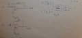
The circuit in post #32 ain't doubling the frequency.
EDIT: added a missing wire.

Hello AG,

I did not say it worked as is so we agree on that point :)
In theory though a log amp (or two) and an anti log amp can produce a squared input wave. They actually make up a multiplier so i dont see why you say it is not squaring anything. Yes it needs work, but after that it should be able to square the input.

However, i find myself in the most uncomfortable position where i seem to have forgotten how to create a true antilog circuit. I have no trouble remembering the log circuit but cant remember how to make the antilog counterpart. Without that we cant square anything as you say.
 

MrAl

Joined Jun 17, 2014
13,702
Dear MaRL and Audioguru,
I found on book different Antilog amplifier, It might help me.fig14 and fig15
Many thanks
SM
I have no problem understanding the log/antilog pair from the math standpoint:
e^log(x)=x
no problem at all.

What i am having a problem with is the drawings i see on the web and what is being passed as a log and antilog amplifier. For example, in one of your pictures we see Figure 7.34 and that shows what they say is a log and antilog amplifier. However, if we look at the supposed "log" amp (the first one) we see that the analysis does not show a log(Vin) or log(Iin) output, and if we look at the supposed "antilog" amp the analysis does not show an e^Vin response either.
What the first amp does show is this:
Id=Is*e^(Vd/K)
log(Id/Is)=Vd/K
Vd=K*log(Id/Is)
and expanded:
Vd=K*(log(Id)-Log(Is))

So if we really want log(Id) we need to do this:
K*log(Id)=Vd+K*log(Is)
log(Id)=Vd/K+log(Is)
So you see there is an added addition of log(Is) and division by K that is required to get the natural log of the current, and because there is an additive term the output of the first amp in 7.34 is not even proportional to the log of the current.

The antilog section is even worse it does not take the true antilog of its input.
The equation is:
Id=Is*e^(Vd/K)
so when we apply Vd we dont get e^Vd we get Is*e(Vd/K) which is not the same.
To try to get e^Vd we have to do this:
Id=Is*e^(Vd/K)
Id/Is=e^(Vd/K)
Id/Is=(e^Vd)^(1/K)
(Id/Is)^K=e^Vd

so we have to be able to take the Id/Is up to a constant power.
Is this even possible.

So either there is a trick that i forgot or this just does not work because we cant take Id/Is up to a power without a log/antilog circuit, which we have not yet constructed properly.

The other problem i think is how do we take the antilog of a negative number using a diode. The only way seems to be that we need to take the reciprocal of the antilog of the absolute value of the negative number. We cant take the reciprocal of a number without a log/antilog amplifier which we did not yet create.
A second way is to add a positive number to the negative number, creating a smaller positive number, take the antilog of that (always positive now) and then divide by e^N where N is that larger positive number.
This requires too much range in voltage i think but ewe can look more at that.
But getting the antilog of a positive number would have to be done first, which doesnt seem to work either.

Think about it, see what you think.
 

Thread Starter

Saviour Muscat

Joined Sep 19, 2014
187
Dear MrAL,
If we use simpler log and antilog amplifiers(fig 16, fig17)
Log Amplifier fig16
Vin/R=Is*e^Vf/nVT
Vin/R*Is=e^Vf/nVT
In(Vin/IsR)=Vf/nVT
Vf=-Vout
Vout=-nVT*In(Vin/IsR)
Vout porortional InVin


for Antilog Amplifier fig17
VR=IR=IsRe^Vin/nVT
Vout=-VR
Vout=IsRe^Vin/nVT
Vout porportional e^Vin

Are these circuits suffice my requirements to implement the analog multiplier(fig18)?
I don't know how to see the circuit works because I am little bit confused.

Thank you for your help,
SM
 

Attachments

Last edited:

Thread Starter

Saviour Muscat

Joined Sep 19, 2014
187
Dear all,
I did the derivation for Log and Antilog amplifiers, then I derived the analog multiplier as seen in the photos attached.
The end result was -(sinx)^2=-(1/2-cos(2*x)/2)//
Please confirm the answer
I am asking, why the simulation isnt correct?

Could someone help me!
Thank you in advance for your help
Saviour Muscat
 

Attachments

Thread Starter

Saviour Muscat

Joined Sep 19, 2014
187
Dear members,
Please could someone give me some feedback regarding my thread? because my deadline to hand my coursework has almost come.
I know you have other things to do, I did my utmost to get the circuit working but with no success, I appreciate all hints and ideas
 
Top