Facebook
 Google
 GitHub
 Linkedin
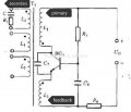
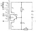
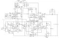
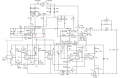
I need to produce oscillations using 2P 3S transformer coupled oscillator. CI have attached the circuit diagram also. I have tried to implement it in Multisim many times, but I am unable to get oscillations. Can anyone help please? I really need to complete this task.
Attachments
-
 19.6 KB Views: 37
 -
 385.2 KB Views: 37