Crystal Oscillator Design

Thread Starter

baranta

Joined Jan 11, 2025
8
Hi, I have multiple questions about crystal measurements.
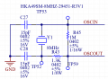
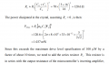
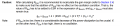
My MCU is STM8AF & I have a crystal with these specifications: 8MHz, ESR=50ohm, C0=5pF, CL=15pF and Typical Drive Level is 50 micro W and Max Drive Level is 300 micro W. I see conflicts in measuring drive level in different documents (I attached related parts)... When I use a current probe my drive level is a lot more than 50 and when I use 1pF active probe there will be much less drive level! I don't know which one to rely on!
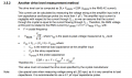
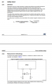
Additionally, I attached Safety factor and gain margin sections ... does RExt affect gain margin? according to the formula it does! but according to safety factor measurement and formula RExt doesn't influence SF! so should we remove it during SF measurement or not? aren't SF and GM correlated? if so, why don't they share same point of view about Rext ?
Thanks in advance,
(the documents are AN2867 from ST and Crystal_Oscillators from Digital Electronics autumn 2014)
 

Attachments

0ri0n

Joined Jan 7, 2025
165
When I use a current probe my drive level is a lot more than 50 and when I use 1pF active probe there will be much less drive level! I don't know which one to rely on!
The methods shown in the various app notes deliver only rough aproximations of the crystal drive level. Measuring the current flowing into the crystal does not tell you the actual current flowing through the motional resistance Rm. Same thing applies to trying to calculate the dissipation inside the crystal from the voltage across the crystal or the voltage across the loading cap at the input of the gate.
 

Bordodynov

Joined May 20, 2015
3,430
By the way, I calculated the average quartz power. I took the voltage on it and multiplied it by its current. Then I averaged it. With Rext=1K, it turned out to be large. I calculated the power at three Rext values and plotted a graph using three points. Please note that I used a 3.3V supply voltage. When powered by 5 V, there will be a lot of power.
 

Thread Starter

baranta

Joined Jan 11, 2025
8
By the way, I calculated the average quartz power. I took the voltage on it and multiplied it by its current. Then I averaged it. With Rext=1K, it turned out to be large. I calculated the power at three Rext values and plotted a graph using three points. Please note that I used a 3.3V supply voltage. When powered by 5 V, there will be a lot of power.
This is my circuit, I use an active probe to calculate crystal voltage(between TP52 and TP 53). when I multiply this value with the crystal (current from current probe) I get 1.013mW which is way larger than 300uW (max DL according to crystal datasheet) but when I multiply the same crystal current powered by 2 with RL, I receive 72.45uW which is very smaller than 1.013mW. I dont know which one to rely on...
 

Attachments

BobTPH

Joined Jun 5, 2013
11,484
For microcontroller crystals, I have just used these simple simple guidelines.

1. Set the drive based in the recommendation from the micro’s datasheet for the crystal frequency.

2. Set the caps to the nearest standard value below 2 x load capacitance (27p for your example.)

3. Place the crystal and caps very close to the chip.

And it always worked.
 

Thread Starter

baranta

Joined Jan 11, 2025
8
For microcontroller crystals, I have just used these simple simple guidelines.

1. Set the drive based in the recommendation from the micro’s datasheet for the crystal frequency.

2. Set the caps to the nearest standard value below 2 x load capacitance (27p for your example.)

3. Place the crystal and caps very close to the chip.

And it always worked.
I am aware of the general guideline but I need to calculate Drive Level precisely for any protentional issues in long term...
 

0ri0n

Joined Jan 7, 2025
165
By the way, I calculated the average quartz power. I took the voltage on it and multiplied it by its current.
It may seem obvious at first to just multiply the voltage across the crystal with the current flowing into the crystal but that will, in this particular case, not give you crystal dissipation. If you have the time and leisure, replace your crystal with it's equivalent circuit and plot the power inside the crystal motional resistance Rm.

This is my circuit, I use an active probe to calculate crystal voltage(between TP52 and TP 53). when I multiply this value with the crystal (current from current probe) I get 1.013mW which is way larger than 300uW (max DL according to crystal datasheet) but when I multiply the same crystal current powered by 2 with RL, I receive 72.45uW which is very smaller than 1.013mW. I dont know which one to rely on...
Multiplying voltage and current only works well at series resonance, where the crystal is basically reduced to a resistor. In a Pierce oscillator the crystal behaves like a large inductor in series with a small resistor (ESR) and multiplying the rather large voltage across this RL-circuit with the current flowing through does not tell you the power dissipation in the series resistor. The error will be very large. Best way imo would be to multiply the squared current with the crystal ESR, which you have to calculate first based on Rm, C0 (both from the datasheet) and the actual in circuit loading capacitance CL of the crystal.
 

0ri0n

Joined Jan 7, 2025
165
See. Pq=PR5=20 uW.
Thank you very much, that was swift. 20uW is quite a difference compared to multiplying voltage across with current through the crystal. Peak-to-peak current into the crystal is around 1.1mA. Based on the crystal ESR and considering the current being (halfway) sinusoidal, I calculate 21uW dissipated in the crystal. Not bad.
 
Top