 Facebook
 Google
 GitHub
 Linkedin
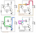
You always have to look at the voltage across a capacitor (not voltage to ground) and that voltage doesn't change unless there is a current flow (charge transfer) through the capacitor.Why are both leads of the cap at 5v in the beginning?
Thus at the start the voltage across the capacitor is zero.
At startup the NPN transistor is off, so the right side of the cap will immediately go to 5V through the 22Ω resistor.
This means the left side of the cap will also go to 5V across the 330kΩ resistor (since the voltage across it is still zero as no current has yet flown through it).


") ), please help me with the sim on ltspice. I tried .tran 5m but when I hit Run a window pops up with the x-axis 0-5ms but nothing else happens. Anywhere I click it shows as a straight line thru 0.
), please help me with the sim on ltspice. I tried .tran 5m but when I hit Run a window pops up with the x-axis 0-5ms but nothing else happens. Anywhere I click it shows as a straight line thru 0.


