Oscillator circuit explanation

Thread Starter

quique123

Joined May 15, 2015
405
working on an Arduino project powered from an "auto-shutting OFF" battery pack, I learned about oscillator ckrcuits used to draw power from a battery pack momentarily in order to keep it from shutting off.

I found this post: https://www.dorkbotpdx.org/blog/paul/battery_pack_load

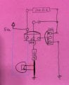
And I'm trying to understand how it works. I understand how a capacitors, inductors and bjt's work. But how does an oscillator circuit put these elements together as in this example, to make an led blink?

I made this circuit on a breadboard and it works:
 

Attachments

crutschow

Joined Mar 14, 2008
38,504
This LTspice simulation below shows that the circuit does not appear to operate as advertised.
The current through the 22 ohm resistor is a sawtooth, not a short pulse.

upload_2018-8-12_0-53-24.png

You would need a different circuit to get a short pulse.
For example, below is a PWM circuit using CD40106 hex Schmitt trigger inverter gates. The PWM duty-cycle is adjusted such that it generates a ≈20ms pulse every 1.3s.

The six gates in a package are connected in parallel to give a higher output drive current.

It uses very little power other than that from the periodic 220mA pulses.

upload_2018-8-12_1-20-42.png
 

Colin55

Joined Aug 27, 2015
519
The circuit does work but it want to be as in the arrangement of circuit #2:
LED_Flasher.gif

The circuit starts by the 330k turning ON the PNP transistor very slightly. The 10u is uncharged.
The current through the collector-emitter of the PNP transistor turns ON the NPN transistor a small amount.
This brings the right-hand lead of the 10u towards the 0v rail.
The left lead of the 10u tries to fall also but it is restrained by the base of the PNP transistor.
Pulling the leads apart like this does one thing. It allows the 10u to charge and this causes current to flow through the 10u and the emitter-base of the PNP transistor.
This causes the PNP transistor to turn ON much harder and the current through the c-e leads also turns on the NPN transistor very hard.
This puts a very high current through the 22R and also the LED in the emitter of the transistor to produce a very bright flash.
The 10u charges very quickly because there is virtually no current limiting resistors in the charging circuit.
As it gets to the point of being fully charged, the current flowing through it decreases to a very small amount and this current is flowing in the emitter-base circuit of the PNP transistor.
It gets to a point that the transistor starts to turn OFF and the current through the 22R decreases so that the voltage across the 22R reduces and the right lead of the 10u rises towards the 5v rail. The left lead follows and the voltage on the base of the PNP transistor actually rises above the 5v rail and as soon as it rises to the value of 4.4v, the PNP transistor completely turns off and the LED is off for a very long time.
The only component in the circuit that will discharge the 10u is the 330k and it does this very slowly and then it starts to charge the 10u to start the next cycle.
 

Thread Starter

quique123

Joined May 15, 2015
405
OK Im beginning to see how colin555 circuit works. I see that he and Dana added a 1k & 10nF cap in parallel and I'll get to that later.
So when powered on, current flows thru the 330k to the base if the pnp, which turns on the npn a little as well?

IS it because the 22 ohm R is the path of least resistance so it flows thru the cap and to the pnp base?
 

crutschow

Joined Mar 14, 2008
38,504
So the addition of R4 and C2 allows the circuit to work as a short duration pulse generator.
My simulations show that the pulse width of this circuit is less than 1 ms.

According to the article, his battery pack needed at least 10ms.
Adding 250 ohms in series with C1 increases the pulse width to about 20ms, the article design value.

Dana, you might check and see if your simulator gives similar results.
 
Last edited:

danadak

Joined Mar 10, 2018
4,057
My sim at 250 ohms in series C1 gives 3 mS, tried 1K and sim
went back to < 1 mS.

Trying < 250 ohms (pulse < 1mS again) and 500 ohms (still < 1mS)
makes one feel this circuit not exactly predictable.

Regards, Dana.
 

crutschow

Joined Mar 14, 2008
38,504
So when powered on, current flows thru the 330k to the base if the pnp, which turns on the npn a little as well?
That's during startup.
But the interesting operation is during the steady-state pulsing so I'll attempt to describe that with the aid of the simulation waveforms below.
As can be seen, during the off portion of the cycle, the PNP base voltage (yellow trace) starts from near double the 6V supply voltage (about 11V) and falls with a time-constant of R3C1.

When the PNP base emitter voltage (red trace) reaches about -0.6V at the end of the fall it starts to turn on.
This also turns on the NPN immediately, pulling its collector voltage (blue trace) to zero
This rapidly discharges C1 with an R2C1 time-constant through the base of Q2, and when Q2's base current drops below its turn on value, Q2 starts turning off.
This turns off Q1, causing the right side of cap capacitor to rapidly rise to 6V and the left side of the capacitor to also rise 6V from about 5.3V to 11V (Q1 Vbe to about -5V),

So now Q2 is fully turned off for the start of the next cycle.

Make sense?


upload_2018-8-12_12-2-25.png
 

danadak

Joined Mar 10, 2018
4,057
If your trying to generate a pulsed load to keep the battery from shutting off
use the Arduino PWM to pulse a load periodically ......

Just an NPN (if current >~ 20 mA) and a load R and a base limiting R from
Arduino to NPN base.

You have to take care of Arduino startup case, same is true for any external
osc. What are those requirements by battery pack to start up ?

Regards, Dana.
 

crutschow

Joined Mar 14, 2008
38,504
My sim at 250 ohms in series C1 gives 3 mS, tried 1K and sim
went back to < 1 mS.

Trying < 250 ohms (pulse < 1mS again) and 500 ohms (still < 1mS)
makes one feel this circuit not exactly predictable.
Interesting.
My sim shows the pulse increasing with the value of the resistor, being about 66ms for a 1kΩ value.

Don't see how it reduces with an increase in value. :confused:
Perhaps the difference is related to the default Beta values for the transistors.
 

danadak

Joined Mar 10, 2018
4,057
Of course there is the old standby unbalanced multivibrator -

upload_2018-8-12_15-46-10.png

Left hand transistor pulsing to ground ~ 5 mS.

Regards, Dana.
 

Thread Starter

quique123

Joined May 15, 2015
405
Thanks.

I don't want to use the Arduino to keep the battery pack because I want to save power to keep the battery pack as charged as possible.

I still don't understand what makes the led blink. My first doubt is, why doesn't the current flow through the 22 ohm resistor first and thru the cap, instead of through the 330k and to the base of the 3906?
 

Colin55

Joined Aug 27, 2015
519
My first doubt is, why doesn't the current flow through the 22 ohm resistor first and thru the cap

Current can only flow through the capacitor when one lead is at a different potential than the other.
In the beginning, both leads are at the same level of about 5v
 

Thread Starter

quique123

Joined May 15, 2015
405
OK and does the right side of the cap turning 0v due to low current flowing thru npn c-e?

Why are both leads of the cap at 5v in the beginning?
 
Last edited:

Thread Starter

quique123

Joined May 15, 2015
405
No I'm sorry. I'm slow and I didn't study electronics. I just tinker

I'm trying to find youtube videos because Un very visual but I haven't found one of an oscillator circuit like this.
 
Top