Facebook
 Google
 GitHub
 Linkedin
Hello,
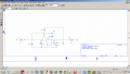
There IS a difference between your schematic and the one of forrest mims.
Yours has 10K / 10K on the + input of the first opamp.
The one of forrest mims uses 27K / 100K on the + input of the first opamp.
That means that the switching points of the circuits are different.
Bertus
There IS a difference between your schematic and the one of forrest mims.
Yours has 10K / 10K on the + input of the first opamp.
The one of forrest mims uses 27K / 100K on the + input of the first opamp.
That means that the switching points of the circuits are different.
Bertus


 . I am so hoppy!