Orcad 16 problem with simulation, wrong results

Thread Starter

ArakelTheDragon

Joined Nov 18, 2016
1,362
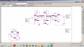
This may be do to my fault, but I am trying to simulate a functional generator with orcad, I tried many circuits for sine wave generation and none of them work. I get a flat line signifying my being dead state or false results.

When I simulate this circuit on Orcad Capture, I get the following graphic depending on the time I set for the Transient Simulation.
This circuit is only the first step from a functional generator, when I simulate the whole generator, I get the same result.

I got the circuit from here:
https://www.instructables.com/id/THE-SIMPLEST-FUNCTION-GENERATOR-BUILT-ON-A-BREADBO/
 

Attachments

crutschow

Joined Mar 14, 2008
34,280
Oscillators often don't start in a Spice simulation, since the usual initial DC bias calculation before the transient simulation can put the circuit in a quasi-stable state and there's no circuit noise that would start the oscillations as in a real circuit.

Try using the .ic command to cancel the initial DC calculation, or ramp up the DC supply voltages at the start to see if that helps.
 

Thread Starter

ArakelTheDragon

Joined Nov 18, 2016
1,362
How to use the .ic command, what do you mean by ramp up? Increase to +-15V?

One of my biggest problems is why is the result different if I change the time to which its simulated? The graphics is different only depending on the time like in the screenshots, is this do to no noise?

I did: "Skip the initial transient bias point calculation".
 

Thread Starter

ArakelTheDragon

Joined Nov 18, 2016
1,362
Ramping up the voltage LED to getting square impulses on the sin wave output. I am guessing that if I put sin wave power supply on the power supply of the last operational amplifier, I will get a sine wave. But that means I have to put the voltage that I need to get on the output as a power supply on every operational amplifier (1 for square, 1 for triangle, 1 for sin wave)?
 

Thread Starter

ArakelTheDragon

Joined Nov 18, 2016
1,362
The supply voltages of everything were +-5V, now they are pulse +-5V at 1000Hz, 50% duty cycle. I will try to use the VDC source and connect the "+" of the VDC to +power supply, and another VDC with "-" to -power supply. Or I can use 1 VDC at 10V and connect it to "+" and "-" power supplies, since it will get divided by 2.

Edit: The circuit is the one from the link I gave, but the signals are not in your post, only the circuit.
 

crutschow

Joined Mar 14, 2008
34,280
I just realized that the problem is, you have the plus and minus inputs on the op amp interchanged.
Reverse those and it should work.
 

bertus

Joined Apr 5, 2008
22,270
Hello,

The V4 at your converter schematic should be symetrical around the 0 Volts.
As I see it now it is between 0 and 5 Volts.
Try the circuit with +2 and - 2 Volts.

Bertus
 

Thread Starter

ArakelTheDragon

Joined Nov 18, 2016
1,362
I know how it works and how to change the frequency its the same as mine.

The first operational amplifier determines the frequency and creates a pulse signal. The frequency is 1/2*C3*R9.
The second operational amplifier integrates and turns the signal into triangle.
The third operational amplifier changes it to sin wave and the 4th amplifies.
 

SLK001

Joined Nov 29, 2011
1,549
Put a NO switch between C4 and the opamp and set it to close at some time after T=0. A "failed to converge" error usually means that something is oscillating.
 
Top