opamp lv 258 corrections

Thread Starter

barg

Joined Dec 23, 2015
111
Hello Everyone,

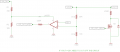
I am using a 24v battery to run a motor and need to make a low voltage cut off when the measured output voltage reaches 20v or bellow. for that i am using a N-fet with lm258 as the attached schematic.

5v Is from lm317.

i am not sure if all the resistors values are correct or the connections I drew, appreciate if any of you can advice for any corrections needed in my schematic?

Thank you in advance,

Barg
 

Attachments

Alec_t

Joined Sep 17, 2013
14,314
R15/16 are ok, but R7 could be a lot smaller (say 220 R) so that the FET gate capacitance charges/discharges quicker.
Note that with only 5V available for the FET gate the FET needs to be a 'logic-level' type to ensure it turns on fully.
 

AlbertHall

Joined Jun 4, 2014
12,346
The LM258 maximum common mode voltage is positive supply minus 1.5V but this circuit is using the inputs equal to the positive supply.
Change R15 to 56k and connect the inverting input to a potential divider, 3.3k to GND and 2.2k to +5V so the circuit now uses a 3V reference.
 

Thread Starter

barg

Joined Dec 23, 2015
111
Thanks Albert and Alec,

I also didn't noticed the -1.5v for the common output, so I added R1+R2 as I prefer higher driving voltage to the gate which I am not sure this solution is correct now.. attached is the revised schematic with this change and Alec suggestion to R7=220R. can you please advice if this change can work correctly?
 

Attachments

AlbertHall

Joined Jun 4, 2014
12,346
No, it won't work with those values. The supply current for the LM258 is 0.5mA and that current through 32k will drop 16V even without R2, leaving just 4V for the amplifier when the supply is down to 20V. A lower value for R1, 820Ω, and replacing R2 with a 12V zener diode will keep the amplifier supply stable (or use a 12V regulator).

There is another problem. When the voltage drops and the FET turns off the load current, the voltage will rise again and turn on the FET again. This process will repeat. This could be fixed by adding hysteresis around the amplifier, but it would need some estimate of how much the supply voltage will rise when the FET switches off.
 

Thread Starter

barg

Joined Dec 23, 2015
111
Thanks Albert,

I think I will use a 12v reg to the op power pin also for the ref, please advice if the attached looks ok (ignoring for now for r15,r16 values)?

Regarding the Hysteresis, if considering a V jumps of 5%+- around th, can you define the resistors values? also can you advice how many and where they are needed?
 

Attachments

AlbertHall

Joined Jun 4, 2014
12,346
The reference must be at least 1.5V below the positive amplifier supply voltage.
The values for setting hysteresis will depend on the values used for the reference and R15, R16.
Another way of getting hysteresis is to latch the 'off' state until the power is removed. This can be done with a diode between the amplifier output (cathode) and non-inverting input (anode).
 

Thread Starter

barg

Joined Dec 23, 2015
111
I have changed that now to ref=5v, also updated R15,R16 as attached. please advice if that's ok? and which resistors should I add for the 5% hysteresis?

Thanks,
 

Attachments

AlbertHall

Joined Jun 4, 2014
12,346
Add a 300k resistor from amplifier output to non-inverting input and add a 270k resistor across R16 (makes the effective value of R16 9.66k)
This gives thresholds of 20V and 21V.
 
Top