OpAmp labels

Thread Starter

cmdettmar

Joined Sep 3, 2020
3
I can work a multi-meter, but am not very knowledgeable about electronics.
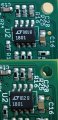
I am trying to diagnose a difference in sensor gain between 2 different batches of PCBs. Does the number on the linear technologies OpAmp next to the logo have meaning, or is it just a batch number or something?
[LT] 001-e3 vs [LT]812-e3
1801 1801

IMG_20200903_104943721.jpg
 

Attachments

MisterBill2

Joined Jan 23, 2018
27,522
LT1801 dual op-amp.
There are two different numbers, the one that is changing is the manufacture date code, the one not changing is the type number. THAT relates the device to a data sheet that describes the characteristics. Those include nominal gains, offset voltages, and frequency response. and a whole lot of other properties.
 

MrSoftware

Joined Oct 29, 2013
2,273
To address your question about different gains; the resistors on those two boards appear to be different. The top image shows a couple of 1k resistors, the same resistors on the bottom image are unlabeled so they could possibly be different. Without a schematic I can't say for sure if that's significant, but that would be a good place to start.

If the batches are supposed to be the same, maybe someone goofed on the BOM for one of the batches and had some wrong parts put on. Or even if they are supposed to be different, the BOMs may hold the key. If you have access to the BOMs used for the actual assembly, it might be easier to compare the BOMs than to physically compare the boards.
 
Last edited:

MisterBill2

Joined Jan 23, 2018
27,522
How much different are the differences in sensor gain values? probably the first easy check is to measure all of the resistors on the most different sensors and see if it is a component difference issue. Most parts are not perfectly on value. It might even be a wrong component problem. It could even be leaking capacitors that have different leakage resistances.
We are not shown the actual sensor elements, so they may even be some of the sensors that I worked in the development program for. There were all sorts of issues with those PVDF sensor elements at the time. If the sensor is a vibration/shock wave detection device, you need to be aware that the cleanliness of the circuit board, and the humidity in the testing area can also have an influence. AND those brass eyelets anchoring the sensor element make a great deal of difference as well.

AND I certainly hope that they fired that new lab manager who they hired right before the big engineering layoffs.
 

MrSoftware

Joined Oct 29, 2013
2,273
To add one more tidbit; parts substitutions are common on new batches of boards, and errors can be made there. If a part became obsolete, or a better price was available with a different brand, etc.. and someone accidentally picked the wrong replacement part, then you can end up with boards that don't work as intended. The final BOM should show what was actually used on the boards. It's also possible someone loaded the pick and place wrong, in which case you'll have to compare the physical boards, but I think this is less likely.
 

Tonyr1084

Joined Sep 24, 2015
9,744
In this case:
[LT] 001-e3 vs [LT]812-e3
they're just date codes.

I know an inspector who rejected a board because the part (2N2222) was used in four places on a small board. The date codes didn't match on all the parts so (s)he rejected the board from the supplier. Engineers supported his(her) rejection even though it was a small signal amplifier board. The boards (many) went back to the manufacturer for repair. They did nothing but send them back to us. They came across my desk so I inspected them. Nothing had been changed. I accepted the boards.

The 2N2222's were metal can type TO-3 or TO-9 (from memory). It's been a few years.
 
Top