is not specified in the delivery I only have the following data:
Design and build an amplifier, even multi-stage, that satisfies the following characteristics:
• Non-inverting gain
• The output signal must be between 0 and 5V +/- 5%
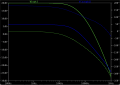
• The frequency response must have a low-pass characteristic with a cutoff frequency equal to
40kHz at +/-10%
Assemble and characterize the amplifier, in particular measure the absorbed power, the frequency response in module and phase and the transient response (trise and tfali) considering pulses of 20µs duration and 0.5V amplitude (between -1.5V and - 1V)
is not specified in the delivery I only have the following data:
Design and build an amplifier, even multi-stage, that satisfies the following characteristics:
• Non-inverting gain
• The output signal must be between 0 and 5V +/- 5%
• The frequency response must have a low-pass characteristic with a cutoff frequency equal to
40kHz at +/-10%
Assemble and characterize the amplifier, in particular measure the absorbed power, the frequency response in module and phase and the transient response (trise and tfali) considering pulses of 20µs duration and 0.5V amplitude (between -1.5V and - 1V)
Ok then the specified output is 5v, which is probably RMS so the peak is 7.071 volts.
The specification of 40kHz is going to mean you need a response I would think up to at least 100kHz, although they do not seem to specify that either.
Op amps with a slew rate of just 1v/us will not work up that high at that voltage. You'll need an op amp that can handle at least 100kHz.
If you like, you can work out the purely theoretical circuit (where the op amp is perfect) and then figure out what op amp you need later.
Do you have an idea about how to do this?
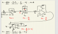
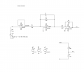
That is, choose the values you need for the circuit you posted earlier (see attachment).
I am not sure why you show so many op amps though.
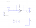
I have some questions, the first one, for the low-pass filter I used a small capacitance so that at high frequencies it has a very high impedance, is this a correct statement? Furthermore, I took the values of the resistors in such a way that they had a value very similar to the required gain, but I could actually use them even 10 times larger, the ratio was indifferent and did not change.
Furthermore, to set the level shifter I used a resistor divider in such a way as not to use an additional power supply (even if this could cause a variation in the tolerances in the design phase, but it seemed better to me than using an additional power supply) Finally, input I used a buffer to have a lower distortion of the input signal, but it is generally used to power a load with a signal source with high internal resistance.
Sorry if I ask a lot of questions, but I have to justify every single step and component I used.
I have some questions, the first one, for the low-pass filter I used a small capacitance so that at high frequencies it has a very high impedance, is this a correct statement? Furthermore, I took the values of the resistors in such a way that they had a value very similar to the required gain, but I could actually use them even 10 times larger, the ratio was indifferent and did not change.
Furthermore, to set the level shifter I used a resistor divider in such a way as not to use an additional power supply (even if this could cause a variation in the tolerances in the design phase, but it seemed better to me than using an additional power supply) Finally, input I used a buffer to have a lower distortion of the input signal, but it is generally used to power a load with a signal source with high internal resistance.
Sorry if I ask a lot of questions, but I have to justify every single step and component I used.
The smaller the capacitance value the higher the impedance regardless of the frequency, but yes, at very high frequencies you would have to use a very small capacitance.
Why do you have a buffer on the input? It's true that the buffer has a nice high input impedance, but the next stage as a 1.8k value for R1 the input resistor. Are you saying that 1.8k is not high enough for the signal source to operate properly?
Your voltage divider puts out about 2.7 volts and the gain of the last stage is over 5. 5 times 2.7 is greater than 10, the voltage of the positive power supply.
Do you see the problem there?
It still looks like you need a better op amp though with a faster slew rate. Do you see why?
The smaller the capacitance value the higher the impedance regardless of the frequency, but yes, at very high frequencies you would have to use a very small capacitance.
Why do you have a buffer on the input? It's true that the buffer has a nice high input impedance, but the next stage as a 1.8k value for R1 the input resistor. Are you saying that 1.8k is not high enough for the signal source to operate properly?
Your voltage divider puts out about 2.7 volts and the gain of the last stage is over 5. 5 times 2.7 is greater than 10, the voltage of the positive power supply.
Do you see the problem there?
It still looks like you need a better op amp though with a faster slew rate. Do you see why?
So the capacitance of 1nF isn't small enough? With a 1.8 kOhm resistor I amplify the signal correctly. At the last stage I have a gain of 4.7 V/V, I don't understand where the problem is?
So do you think I should change the amplifier? Because LM358 seems to me to be the best among the opamps I can use
So the capacitance of 1nF isn't small enough? With a 1.8 kOhm resistor I amplify the signal correctly. At the last stage I have a gain of 4.7 V/V, I don't understand where the problem is?
So do you think I should change the amplifier? Because LM358 seems to me to be the best among the opamps I can use
Well look at the last stage gain and figure out what the maximum voltage on the output of that will be. If the peak goes over the power supply voltage, it will not work it will clip the output wave. That's the ideal case, but the practical case would be even worse because you probably have to have the peak voltage be less than about 2 volts less than the power supply. Since the power supply is plus 10 volts, the maximum signal amplitude on the output would be 8 volts. Since you intend to use this for AC, that would mean the peak of the test sine would be 4 volts. This means your maximum AC output would be 4 volts peak, although the maximum amplitude is still 8 volts. So look at that and figure out if your max output voltage is going over 8 volts. From your schematic, it looks like it is.
Your capacitor is chosen based on your low frequency cutoff point when combined with the feedback resistor.
Do you know how to calculate the cutoff frequency?
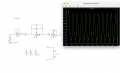
With the LM358, your maximum output voltage (peak) is about 1.99 volts at 40kHz. If you go over that voltage, the output will get distorted and it could be very badly distorted. This makes the LM358 incompatible with your application unless you can keep the voltage that low.
The choice of an op amp involves at least the slew rate and small signal bandwidth.
Sorry for having modified the diagram and having increased the supply voltage to 12.5 V, in order to avoid the risk of saturation, sorry, how can I prevent problems that I encounter during the assembly phase?
Because my circuit in the simulation phase works.
So calculating the cut-off frequency, the question about the capacitor was related to whether taking a 1n or 1μ capacitor changed if obviously I always maintained the same cut-off frequency.
I had checked the narrow signal bandwidth and the LM358 was perfect for my application. But LM358 seemed the best for my application because I can't use the MCP6292 due to its low power supply, UA741 you told me is obsolete.
Could I perhaps use the OP07?
Sorry for having modified the diagram and having increased the supply voltage to 12.5 V, in order to avoid the risk of saturation, sorry, how can I prevent problems that I encounter during the assembly phase?
Because my circuit in the simulation phase works.
So calculating the cut-off frequency, the question about the capacitor was related to whether taking a 1n or 1μ capacitor changed if obviously I always maintained the same cut-off frequency.
I had checked the narrow signal bandwidth and the LM358 was perfect for my application. But LM358 seemed the best for my application because I can't use the MCP6292 due to its low power supply, UA741 you told me is obsolete.
Could I perhaps use the OP07?View attachment 314346
It could be the simulation model making it look OK. All the model has to do is have a little more slew rate like 0.7v/us and it will work up to 2.8v peak or so at 40kHz.
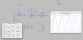
However, it appears that you are only testing at around 200Hz, not 40kHz. That will not show the results at 40kHz. Try testing with a 40kHz wave and post the output signal here like you just did.
There is another point to be made also. That is, since this is a low pass filter with cutoff at 40kHz, that means that it is probably meant to work at frequencies that are higher, maybe even much higher. The good news is that as the wave amplitude decreases after 40kHz, the output peak will not have to go as high, and so you may get away with a lower slew rate like that 0.7v/us quote. It would be best to go even higher than that though, I would think at least 1v/us, but do some more tests see what you get on the output.
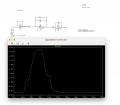
If you can do a Fourier analysis on the output wave that would tell us how bad or how good it is. If you can't do that then look near the zero crossing and see if you see anything that looks unlike a real sine wave. If you like, you can also generate a separate sine wave with the same amplitude and phase as the output and plot that with the output wave. You can then eye up some deviation if there is any in the output. The Fourier analysis is the best method though if you can do that.
Sorry for having modified the diagram and having increased the supply voltage to 12.5 V, in order to avoid the risk of saturation, sorry, how can I prevent problems that I encounter during the assembly phase?
Because my circuit in the simulation phase works.
So calculating the cut-off frequency, the question about the capacitor was related to whether taking a 1n or 1μ capacitor changed if obviously I always maintained the same cut-off frequency.
I had checked the narrow signal bandwidth and the LM358 was perfect for my application. But LM358 seemed the best for my application because I can't use the MCP6292 due to its low power supply, UA741 you told me is obsolete.
Could I perhaps use the OP07?View attachment 314346
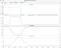
Subsequently I have to consider the transient response (Trise and Tfall), considering pulses of 20µs duration and 0.5 V amplitude Could someone explain to me why those two humps form during the ascent and descent
Subsequently I have to consider the transient response (Trise and Tfall), considering pulses of 20µs duration and 0.5 V amplitude Could someone explain to me why those two humps form during the ascent and descentView attachment 314594
Ok thanks. This helps to understand the entire circuit better, although I still have to ask a question.
That is, what circuit simulator are you using?
I ask because I do not see this behavior in the simulator I am using with the TI model for the LM358. This leads me to think that we need a test of the model itself.
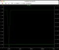
The green output waveform in your previous post looks like crossover distortion, but I do not see why that would occur in your simulator and not in mine.
I can suggest a few tries to help narrow this down.
First, connect a 10k resistor from the output of the last stage to VCC- (which is your minus Vcc of -12.5 volts). See if the output wave improves (you should plot this).
If it does not improve, try disconnecting the resistor R3 from the previous stage and drive it with a pulse source from -1v to +1v, maybe 50us wide and with a 200us period. Do a plot of the output of that last stage op amp U5.
The model seems to be having an issue but it will take a few tests to find out what is causing this.

 Facebook
 Google
 GitHub
 Linkedin