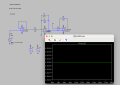
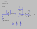
Op amp, I want to use LM358

ericgibbs

Joined Jan 29, 2010
21,532
hi @tonyStewart
Ref your post #20
AAC ruling on Homework, College assignments, we do not post final solutions, only guidelines, so please revise/edit your post.

Moderation.
 
Last edited:

Ian0

Joined Aug 7, 2020
13,228
You might think that if there is nothing in the output signal over 40kHz, then you don't need an op-amp with a bandwidth over 40kHz. Unfortunately, that isn't correct. Your op-amp needs a decent amount of gain and very little phase shift at the cutoff frequency of your filter.
For want of a bad analogy, if you want to catch motorists who exceed the 70MPH speed limit, then the police need cars that can go faster than 70MPH. It's a bit of a hopeless analogy now that there are speed cameras, but it's so bad you won't forget it.

You can achieve the filter you need using a MFB filter and a single op-amp, provided that is has enough gain at 40kHz.
Look at
http://sim.okawa-denshi.jp/en/OPtazyuLowkeisan.htm
and type in K=-10 and fc=40kHz.
 

tonyStewart

Joined May 8, 2012
238
hi @tonyStewart
Ref your post #20
AAC ruling on Homework, College assignments, we do not post final solutions, only guidelines, so please revise/edit your post.

Moderation.
OKEY DOKIE, no need as #19 says enuf.

Minika,

Bonus points.
How would do this differently to limit the out using a single supply output to match an ADC of 0 to 5V input to prevent latchup on CMOS?
Come si farebbe diversamente per limitare l'uscita utilizzando una singola uscita di alimentazione per abbinare un ingresso ADC da 0 a 5 V per impedire il latchup sul CMOS? Spero che tu possa essere in grado di risolvere. Buona fortuna per i tuoi studi.
 
Last edited:

WBahn

Joined Mar 31, 2012
33,075
OKEY DOKIE, no need as #19 says enuf.

Minika,

Bonus points.
How would do this differently to limit the out using a single supply output to match an ADC of 0 to 5V input to prevent latchup on CMOS?
This is a basic homework problem in a course in which they have likely just been introduced to opamps not too long ago -- they have likely never even heard of latchup.
 

WBahn

Joined Mar 31, 2012
33,075
hi I should amplify a signal in the range between -1.5 V and -1, into an output signal between 0 and 5 V, using amplifiers.
with the frequency response which must have a low pass characteristic with the cut-off frequency equal to 40kHz.
I wanted to create this circuit with 3 stages but it is complicated, the overall gain must be -10 V/V.
in the first stage I wanted to put a buffer, in the second a low-pass filter with RC in parallel, and in the third I wanted to put a summing amplifier to obtain the desired gain.
To do this I wanted to use LM358, in your opinion it could be an idea.
I need help with the calculations
This appears to be the same problem you started a thread on two weeks ago.

https://forum.allaboutcircuits.com/threads/electronics-laboratory.198459/

Please, one-topic, one-thread.

Go back and read the comments in that other thread -- you are choosing to ignore some rather explicit hints on how to go about getting the DC transfer characteristic you are looking for.
 

tonyStewart

Joined May 8, 2012
238
The critical learning step foer
This is a basic homework problem in a course in which they have likely just been introduced to opamps not too long ago -- they have likely never even heard of latchup.
I see TY.

The critical step in analyzing this problem is to how to define the Offset.
All level conversions have gain from ratio of out/in and offset from average in to out.
Please review my comments in #14 and answer in #19. Let me know if you understand.
 

MrAl

Joined Jun 17, 2014
13,765
hi I should amplify a signal in the range between -1.5 V and -1, into an output signal between 0 and 5 V, using amplifiers.
with the frequency response which must have a low pass characteristic with the cut-off frequency equal to 40kHz.
I wanted to create this circuit with 3 stages but it is complicated, the overall gain must be -10 V/V.
in the first stage I wanted to put a buffer, in the second a low-pass filter with RC in parallel, and in the third I wanted to put a summing amplifier to obtain the desired gain.
To do this I wanted to use LM358, in your opinion it could be an idea.
I need help with the calculations
I just read that this might be a duplicate thread. WHY create a duplicate thread?

Hi,

You can not get a 5v output from the LM358 at 40kHz no matter what power supply you use, 5v, 10v, 15v, etc. For a 5v peak sine signal the max frequency would be about 15kHz unless you could put up with some very extreme distortion. That's because although the gain bandwidth of the op amp is 1Mhz, the power bandwidth is much more limited and depends on the peak output of the op amp.
This figure is proportional to the output peak voltage, so for a 2.5v peak sine output you might get up to 30kHz. To get up to 40kHz you'd have to limit the output to 1.875 volts peak, but probably 1.5 volts peak would be better.

To figure out the max frequency just divide 75kHz by the output peak voltage. For example, for a 10v peak output 75/10=7.5kHz.
Unfortunately that is the MAX undistorted output which means if you are making a low pass filter you don't want the output to suddenly become distorted once the cutoff freqeuncy is reached. That means you have to figure for an even higher frequency then. If you want a 40kHz cutoff frequency then you may even have to go up to 80kHz which means the maximum peak sine output would have to be limited to about 75/80=0.938 volts peak.

As you can see, the limited bandwidth and slew rate make the LM358 only good for some things not others. It works very well for some things so it is still a useful op amp, but for some applications it just won't fly.

Just so you do not have to ask, it also does not depend on if you are using more than one op amp in cascade to try to increase the maximum power bandwidth. That's because the max depends only on the very last op amp in the cascade. If the last op amp cannot handle the output peak without distortion, it does not matter what you put before that. You could have a 100MHz op amp with 50 volts per microsecond slew rate ahead of that LM358, and that last LM358 would still cause distortion for a peak output that is above that max limit.

It also does not help to use a parallel arrangement of op amps because it is not the output current that causes this limitation it is the slew rate.

There is one possibility I can think of offhand but it would probably be too impractical. If you could drive the negative power rail of one op amp with the output of another with the same gain setting, that would mean the output of the upper op amp would increase twice as much as with just one op amp, and that would mean you could get a total output of two times using just one op amp. If each op amp could do 1v at the required frequency, that would mean the total output peak would be 2v at the required frequency.
This would not be very practical I don't think, if it worked at all.

The right solution is to migrate to an op amp with faster slew rate and usually higher bandwidth too.

The LM358 is one of my all-time favorite op amps, but you do have to be aware of its limitations.
 

Thread Starter

monika.duccoli

Joined Jan 12, 2024
72
I just read that this might be a duplicate thread. WHY create a duplicate thread?

Hi,

You can not get a 5v output from the LM358 at 40kHz no matter what power supply you use, 5v, 10v, 15v, etc. For a 5v peak sine signal the max frequency would be about 15kHz unless you could put up with some very extreme distortion. That's because although the gain bandwidth of the op amp is 1Mhz, the power bandwidth is much more limited and depends on the peak output of the op amp.
This figure is proportional to the output peak voltage, so for a 2.5v peak sine output you might get up to 30kHz. To get up to 40kHz you'd have to limit the output to 1.875 volts peak, but probably 1.5 volts peak would be better.

To figure out the max frequency just divide 75kHz by the output peak voltage. For example, for a 10v peak output 75/10=7.5kHz.
Unfortunately that is the MAX undistorted output which means if you are making a low pass filter you don't want the output to suddenly become distorted once the cutoff freqeuncy is reached. That means you have to figure for an even higher frequency then. If you want a 40kHz cutoff frequency then you may even have to go up to 80kHz which means the maximum peak sine output would have to be limited to about 75/80=0.938 volts peak.

As you can see, the limited bandwidth and slew rate make the LM358 only good for some things not others. It works very well for some things so it is still a useful op amp, but for some applications it just won't fly.

Just so you do not have to ask, it also does not depend on if you are using more than one op amp in cascade to try to increase the maximum power bandwidth. That's because the max depends only on the very last op amp in the cascade. If the last op amp cannot handle the output peak without distortion, it does not matter what you put before that. You could have a 100MHz op amp with 50 volts per microsecond slew rate ahead of that LM358, and that last LM358 would still cause distortion for a peak output that is above that max limit.

It also does not help to use a parallel arrangement of op amps because it is not the output current that causes this limitation it is the slew rate.

There is one possibility I can think of offhand but it would probably be too impractical. If you could drive the negative power rail of one op amp with the output of another with the same gain setting, that would mean the output of the upper op amp would increase twice as much as with just one op amp, and that would mean you could get a total output of two times using just one op amp. If each op amp could do 1v at the required frequency, that would mean the total output peak would be 2v at the required frequency.
This would not be very practical I don't think, if it worked at all.

The right solution is to migrate to an op amp with faster slew rate and usually higher bandwidth too.

The LM358 is one of my all-time favorite op amps, but you do have to be aware of its limitations.
So basically you would advise me to change all the opamps, for example using MCP6292, I would have a greater bandwidth (10 times greater), it also has a slew rate of 7 V/µs compared to 0.3V/µs
 

MrAl

Joined Jun 17, 2014
13,765
So basically you would advise me to change all the opamps, for example using MCP6292, I would have a greater bandwidth (10 times greater), it also has a slew rate of 7 V/µs compared to 0.3V/µs
If those specs are right then yes that would probably be a much better choice.
 

Thread Starter

monika.duccoli

Joined Jan 12, 2024
72
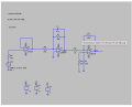
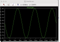
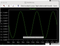
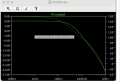
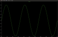
I managed to fix the voltage offset and gain during the simulation, by chance I should add some components to obtain a lower distortion while assembling the circuit, checking frequency response Because I notice a slight distortion of the signalScreenshot 2024-01-31 alle 12.36.32.png
 
Top