 Facebook
 Google
 GitHub
 Linkedin
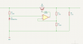
Hello, I would very much appreciate it if anyone can help me understand why the following op-amp circuit is giving me wrong values in simulation. I use Kicad 8 for simulating this. The input voltage is 3.6V with current value of almost 30mA, I expect to recieve an output voltage of 3.3V and almost 30mA output so that can be supplied to ICs further down. The numbers make sense before the Q1 NPN, but after that, the numbers make no sense, including voltage and current numbers through resistors. Could you please tell me what could be wrong in this circuit? Thank you.
Attachments
-
 71.6 KB Views: 27


") . I found a lecture note which in the lecturer was doing the calcualtions of op-amp, so knowing that the power supply gives 3.6V and I need 30 mA at maximum when ICs are in active mode with 3.3V output, I did the calculations. I also assumed the values for R1 and R2.
. I found a lecture note which in the lecturer was doing the calcualtions of op-amp, so knowing that the power supply gives 3.6V and I need 30 mA at maximum when ICs are in active mode with 3.3V output, I did the calculations. I also assumed the values for R1 and R2. 


