 Facebook
 Google
 GitHub
 Linkedin
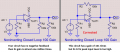
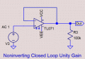
I don't see why this is not open loop?


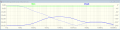
And the .asc files. This should be right but the plots don't look right to me...
And the .asc files. This should be right but the plots don't look right to me...
Attachments
-
1.5 KB Views: 2
-
1.5 KB Views: 1
-
1.6 KB Views: 1


")


