Facebook
 Google
 GitHub
 Linkedin
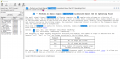
I have this filter circuit, and I would like to calculate the cutoff frequency as I would like to change a few components. I have tried to calculate the transfer function, but I started to get confused about all the stages; therefore, I am now trying to simulate it using LTspice, although I am not sure why the magnitude starts at -46dB. Is that correct, or am I missing something? Is it correct where I have placed the probe? I am a bit lost as I do not see any difference in the plot if I place the probe at the input or the output.
A little bit of information in regards to the circuit: I have set the source voltage to be 10mV equivalent to the max output voltage at 5V excitation of a 2mV/V sensitivity loadcell and a phase of 90, but I am not even sure that is the right way to do it. As per source resistance, I have used the bridge resistance of 350ohm.
If it can help the ADC input is connected to a CS5530.

The Screenshot does not include the mouse so I have placed a label where the probe is

A little bit of information in regards to the circuit: I have set the source voltage to be 10mV equivalent to the max output voltage at 5V excitation of a 2mV/V sensitivity loadcell and a phase of 90, but I am not even sure that is the right way to do it. As per source resistance, I have used the bridge resistance of 350ohm.
If it can help the ADC input is connected to a CS5530.
The Screenshot does not include the mouse so I have placed a label where the probe is
Last edited: