Old Peavey mixing console trips breaker

MisterBill2

Joined Jan 23, 2018
27,720
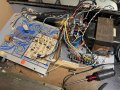
The terminals of the lower 2 output jacks are not "merely touching" the terminals of the upper two, they are, in fact, very deliberately connected and soldered.
So those are not the problem.
I suggest examining the "X" jumpers on the polarity switch, if they touch it will pop the fuse instantly.
AND, I suggest checking those two great big blue electrolytic capacitors for excess leakage. That sort of cap seldom lasts forever.

In that regard, you could power the panel thru a lower wattage rated light bulb and just leave it on for a few hours, to see if the capacitors will reform themselves. That might be the fix, cheap if it works and not a huge waste if it does not work.
 

dendad

Joined Feb 20, 2016
4,641
Last group…odd thing to me—notice the back panel with the 4 1/4” jacks grouped together. Labeled Power Amp Out. Seems odd that the lower two are not “wired” but merely touching the soldered terminals of the other two, and doesn’t appear to be soldered to anything…
That is ok as the barrel of the sockets are all connected to the chassis plate, and so the one blue wire is the connection shared with them all.
 

MisterBill2

Joined Jan 23, 2018
27,720
I am suspecting the huge filter capacitors. 10,000 microfarad seems a huge claim. AND, I did once receive a 2000 watt amplifier to fix that had failed 10,000 mfd capacitors. For testing , if you have or can borrow any high value filter capacitor with a 75 volts voltage rating long enough to verify everything works, you could do a temporary substitution to verify that was the only problem.
If you use that series light bulb scheme, carefully disconnecting one terminal of that capacitor, keeping the wires connected to each other, and not touching anything else, could reveal a failed cap if the series light goes much dimmer.
 
Last edited:

eetech00

Joined Jun 8, 2013
4,709
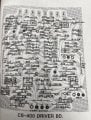
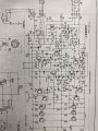
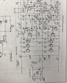
I saw that in my searching, and a couple of others. But for the last couple of years I’m suspecting just about everything of being possible scammers, phishers, hackers, etc., so I was afraid to go any farther, unless someone we trust can verify for me…I’ve had some close calls despite the increased diligence I try and put in…
Hi

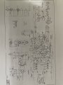
I have an old Peavey PA-600 that I fixed. I fixed it about 6 years ago. I really like the anti-feedback/Vocal equalization circuit it has. Anyway, initially, I didn't have a schematic but after talking to Peavey support, they happily sent me schematics and board assembly info. You might want try them asking them directly. Maybe they will help.
 

Thread Starter

robismod

Joined Sep 22, 2015
371
Hi

I have an old Peavey PA-600 that I fixed. I fixed it about 6 years ago. I really like the anti-feedback/Vocal equalization circuit it has. Anyway, initially, I didn't have a schematic but after talking to Peavey support, they happily sent me schematics and board assembly info. You might want try them asking them directly. Maybe they will help.
Hmmm I thought Peavey was shut down?
I’ll dig a little deeper. Many thanks.
 

Thread Starter

robismod

Joined Sep 22, 2015
371
I am not aware of any such shutdown! SWEETWATER still sells Peavey products, and I take that as evidence that the company is still alive.
Hmmm…I don’t know where I came up with that from, or how. but I surely was convinced in my mind that they were gone. I’ve been mostly away from the pro music scene for many years now, and what dabbling I still do I just haven’t seen anything new from them that I can recall. Glad to know now I didn’t have a clue…(but that’s not new for me haha)
 

Thread Starter

robismod

Joined Sep 22, 2015
371
I hate to ask dumb questions (never stopped me before ) but…
Those two big 10,000 mf 75wdc caps are bridged together and I want to ensure they’re drained —thought about trying the lightbulb drain thing…the big size alarms me a little bit so I don’t want to just touch ‘em with anything (especially me) or take a chance on zapping something. Can I drain them while bridged together, or should I carefully remove the connector strips?
(I swear as I’ve gotten older more quickly lately that I feel I’m getting overly cautious to the point where I sit and look at things for a long time. Trying to muster up the courage to jump back in, like how for many years I didn’t waste much time, got a bit of understanding and then got hands-on. It’s not just in electronics but in other facets of life too. It’s a little worrisome. But, as long as I keep moving forward, I’m good. Just don’t want to get to a point of fear keeping me inactive…I guess it’s a natural thing—after all, I never could have imagined I’d still be here at 65! )
 

dendad

Joined Feb 20, 2016
4,641
Once turned off and unplugged, you can wait a minute or so and measure the voltage with a multimeter set on 100VDC to ensure the voltage is zero.
A 10K 1W resistor across them will help drain the charge but I would think the amp circuit will do that fairly quickly.
 

MisterBill2

Joined Jan 23, 2018
27,720
There are already resistors in place to discharge the capacitors, at least partly.The negative side will be discharged completely.
So now you can follow the power supply circuit and check voltages.
 

Thread Starter

robismod

Joined Sep 22, 2015
371
I know I’m “short cutting” the test procedures, but I’m just dabbling with a few bits of time and seeing if I can narrow it down some…please bear with me…
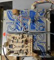
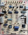
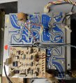
Last night I powered up with new fuse and with the dim bulb tester. Immediate bright light bulb. Then I moved over to the two power amp modules and unplugged a 4 pin harness from each. This time powering up the bulb had a very slight glow in the filament. Plugged power amp boards back in one-at-a-time and found farthest away board when plugged up caused the bright bulb. Pulled the circuit board away from the bottom large heat sink-power transistors assembly to inspect closer. Nothing obvious that I can see…
 

Attachments

Thread Starter

robismod

Joined Sep 22, 2015
371
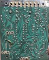
Last night, after looking at the power circuit board again more closely and seeing nothing obvious, I plugged all the connectors in, insulated the board away from the bottom heat sink/outputs section, and powered up. (Again through the dim bulb circuit) and no bright bulb. Mixer fired up normally and fan running. So, I didn’t plug in to that bottom sink/outputs section. I guess my problem is there… here’s the pic again of that section. (I’ll get a pic of the other side tomorrow)
 

Attachments

MisterBill2

Joined Jan 23, 2018
27,720
The next step should be using an ohm meter to check for shorted output transistors. That test is done with the power off and unplugged. That checking should not be too complicated.
Of course, that will not reveal a problem in the driver circuit section, but it is a good way to locate a failed power transistor.
 

Thread Starter

robismod

Joined Sep 22, 2015
371
The next step should be using an ohm meter to check for shorted output transistors. That test is done with the power off and unplugged. That checking should not be too complicated.
Of course, that will not reveal a problem in the driver circuit section, but it is a good way to locate a failed power transistor.
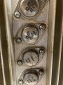
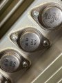
I was able to remove the panel that holds the two amp sections, flipped over and started pulling the transistors to check. Under that one suspect power panel it has 8 total transistors, group of 4 on two sides. 3) SJ6357D and 1) SJ6344. So far I’ve tested “bad” one of the 6357s on each side, but haven’t gotten to the 6344s yet…am I getting somewhere?
 

Attachments

Top