Oil well ignition module

Thread Starter

MarkySparky42

Joined Aug 28, 2022
204
I’d given up on that little circuit but I’d be willing to build something up and test it to the point of “smoke freedom”.

This is a very cleaver approach. I wonder how it would work in temperature extremes. Only way to tell is build it.

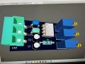
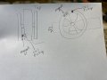
my mini CCFL transformer should be here in a few days. In the meantime I’m going to solder if that trigger circuit you designed with a plug terminal like I had in my first circuit with the wall wart. I’m going to add some mini pots for the resistors so that it can be adjusted (Up, down, left, right, faster, slower).
My son has a cross country meet this morning and afternoon so I can’t get tho this till later. Wife is sick too. Ugh.
 

Alec_t

Joined Sep 17, 2013
15,119
I wonder how it would work in temperature extremes.
Simulation says the post #279 approach should work ok over the temp range -40C to 50C (at least) with no significant change in performance.
Wish your wife well from this side of the pond.

Edit:
Here are the sim results for -60C and +60C :-
TempTest.jpg
 
Last edited:

Thread Starter

MarkySparky42

Joined Aug 28, 2022
204
Free sample from Coilcraft just showed up


So for the above referenced two circuits - I’d just take the direct 350+/- from the existing circuit board I purchased and direct it into the circuit and the magnetic coil should cause it to fire? Or I could use the 555 trigger coil?

If so I can do that.

also, I have two of the pre-made circuits. One has an output HV and GND and the other has two 10uF caps and outputs +HV, GND, -HV

The second circuit board’s 10uF caps run cooler so I’m tempted to use that board. Ideas?
 

Attachments

Alec_t

Joined Sep 17, 2013
15,119
I’d just take the direct 350+/- from the existing circuit board I purchased and direct it into the circuit
Yes.
and the magnetic coil should cause it to fire?
Yes, providing the trigger coil voltage is enough to cause sufficient gate current to fire the SCR.
What are the specified gate voltage and current for the SCR you have?
What is the resistance of the trigger coil? You might need some way of preventing excessive gate current.
Or I could use the 555 trigger coil?
The 555 trigger circuit should do the job. It might need tweaking to suit the SCR properties.
The second circuit board’s 10uF caps run cooler
When driving what load? When driving the post #279 circuit(s) I wouldn't expect the 10uF cap(s) of either HV board to get noticeably warm, since ripple current should be only ~8mA average at typical engine rpm.

I'm unfamiliar with gas engines. Is any form of advance/retard required for the ignition pulse, e.g. to prevent knocking or aid starting?
 

Alec_t

Joined Sep 17, 2013
15,119
Or I could use the 555 trigger coil?
As the HV blanking isn't needed with the post #279 circuits a simpler trigger circuit than the one I previously posted can be used. Here's a suggestion, which still provides amplification of the trigger coil signal :-
CDItrigger3.jpg
No integrated circuit is used.
Your HV supply is modelled in the dotted rectangle.
R2 provides a 0.2 volt offset between the Q1 and Q2 bases, to reduce the risk of spurious triggering of the ignition pulse.
If D1 is present, C1 and the ignition coil can oscillate and dissipate energy. R8 then dissipates only about 200mW so can be conservatively rated at 1W. However, if D1 is omitted the R8 dissipation increases to around 3W, making a 5W resistor advisable.
The SCR gate current is the main determinant of whether or not the SCR can be triggered over the full -60C to +60C temperature range.
 

Thread Starter

MarkySparky42

Joined Aug 28, 2022
204
SO MANY circuits to build and not enough time.

I still feel better supplying the 12VDC to this or any of the circuits I am attempting to build, after the 12vdc automotive voltage regulator.

I obtained all the parts I need to start breadboarding the CDI circuit with the CC transformer that I posted... then I will breadboard up the above circuit and give it a go. In lieu of spinning the magnet on the workbench I will use the trigger circuit we previously constructed (unless you think that this is a bad idea?)...

Field update: the new Schottky diodes brought the "dead" solar panel panel back to life at full strength, but because tech support at Renogy would not / could not recommend that line of action, they gifted me with an additional 100W panel. Now I have a spare.
 

Thread Starter

MarkySparky42

Joined Aug 28, 2022
204
Hello All. Long time no see. Work and medical adventures have kept me away for far too long.
Alec, you designed a simple 555 circuit to simulate my spinning magnet... I have a question about the pulse timing. If the engine runs at 450 rotations per minute that should be 7.5 coil discharges per second. How do I modify your trigger circuit to discharge between say 20 rpm and 500 rpm?

I have been playing with EasyEDA to draw up the schematics, PCB layout and Simulation. I cannot afford DipTrace.

Glad to be back.

- Mark
 

Attachments

Thread Starter

MarkySparky42

Joined Aug 28, 2022
204
I thought your magnet was on the flywheel. If so then wouldn't it be 15 discharges? 450RPM x 2 = 900(because it's a 4 stroke engine) 900 divided by 60(seconds) = 15 discharges
the current ignition system / circuit fires once per revolution of the flywheel. There magnet passes the trigger and the spark plug fires.

the old magneto system may have worked like that but this is how it currently runs. One circle = one bang.
 

shortbus

Joined Sep 30, 2009
10,050
the current ignition system / circuit fires once per revolution of the flywheel. There magnet passes the trigger and the spark plug fires.

the old magneto system may have worked like that but this is how it currently runs. One circle = one bang.
So then the magnet is mounted to the cam not the flywheel?
 

Thread Starter

MarkySparky42

Joined Aug 28, 2022
204
This might be a vocabulary problem on my end. The cool pick up is at 12:00 o’clock high mounted next to the flywheel. There are actually two flywheels to keep the engine balanced.
 

Attachments

Alec_t

Joined Sep 17, 2013
15,119
do you remember the theoretical voltage peak? The physical magnet at max makes 3.5 Volts but I forget the low rpm starting voltage…
You said the trigger coil peaks are about 0.5V amplitude at start-up rpm. That's what the R1/R2/C3 values shown in post #290 give.

Edit:
Your 'scope shot in post #295 seems to indicate that the 555 output pin isn't pulling up well to near the +12V rail.
 
Last edited:

Thread Starter

MarkySparky42

Joined Aug 28, 2022
204
You said the trigger coil peaks are about 0.5V amplitude at start-up rpm. That's what the R1/R2/C3 values shown in post #290 give.

Edit:
Your 'scope shot in post #295 seems to indicate that the 555 output pin isn't pulling up well to near the +12V rail.
You're right. I forgot about low rpm starting voltage. Thanks for remembering. I wonder if this model of 555 is wrong. Maybe I need a 555N or P or something else to get the voltage up and get the timing somewhere between 1 and 10 fires per second. I’m experimenting with tweaking the values of the resistors. More news on that later.

Good news: I was able to get an IC split-fork (I don’t remember the real name) and was able to attach the surface mounted transformer to pins.
 

Attachments

Alec_t

Joined Sep 17, 2013
15,119
I wonder if this model of 555 is wrong. Maybe I need a 555N or P or something else to get the voltage up
All versions of the 555 should work for this project. Bipolar versions have an output voltage a Volt or so below the supply voltage, but CMOS versions should reach virtually the supply voltage unless the output pin is heavily loaded.
When you say 'model', are you referring to a simulation model or a real-world one? If real world, then I wonder if you've got a defective specimen?
 
Top