Oil well ignition module

shortbus

Joined Sep 30, 2009
10,050
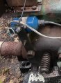
OK, while you call that an "old" engine it's in reality a modern type of F-M engine. It will have bearings and better steel in it and it has a real crankcase that contains oil, not drip cups. When you said you had an old engine I assumed it was like the one I showed.

I know you said a DIY CDI was a learning experience, I don't understand why you ripped the whole ignition out of this. I'd have added to the original trigger system not going to a hall or magnet on the flywheel. The way your headed how are you going to adjust/control RPM's?
 

Irving

Joined Jan 30, 2016
5,131
Here is what I gathered.
the cap takes too long to discharge (without the primary coil and a spark plug) that I can’t tell if the power supply is switching off.
I suspect even with the coil & plug it won't discharge it completely... as long as the SCR turns off it'll be fine. If it doesn't then you have an issue and you may need to reduce the on board capacitance or remove it all together...

Can I use this (and how) to simulate the trigger?
Possibly but it might take longer to get it working... as its only a square wave not a pulse...

Ok. I found the issue. I have an LM555

...

I found an NE556N
Not sure why that should make a difference, they are supposedly identical...

Incidentally the trigger waveform of two spikes won't be seen at the 555 output, that's always going to be a +ve going pulse about 1.7mS wide

But. my bad.. it needs to be a -ve going pulse, because you want the rising edge to trigger the SCR AFTER the falling edge triggers your blanking, which is what you get from the reluctance sensor... As it stands its not a great replacement for the sensor...
 

Thread Starter

MarkySparky42

Joined Aug 28, 2022
204
Ok. Well I have a very nice 555 Square wave generator now. I’ll have the coil, plug and trigger coil back tomorrow afternoon.

mom going to take a closer look at a DC CDI schematic and see what it is I’m doing wrong. I can’t see the next step. Maybe because I sneezing so frequently. As soon as the weather starts to cool off… allergies.
 

Alec_t

Joined Sep 17, 2013
15,119
That Jaycar kit brings back memories. I built up a similar kit back in the day.
Questions:
1) Do you know whether the Enable jumper on the converter module is shorting a pin to ground or pulling it high?
2) Are both terminals of the trigger coil volt-free, or is one inherently grounded to engine chassis by the coil mounting?

Edit:
3) Is the position of the trigger coil adjustable to allow timing adjustments? Depending on the properties of your converter it might take a few mS to switch off the HV supply before the SCR should be triggered.
 
Last edited:

Thread Starter

MarkySparky42

Joined Aug 28, 2022
204
Ok team DC CDI:

im at the well today.
Upgrading the solar charger and adding a 12Vdc voltage regulator. Adding a few other items as well. I have all the ignition parts to bring home (spare set).
 

Irving

Joined Jan 30, 2016
5,131
Questions:
1) Do you know whether the Enable jumper on the converter module is shorting a pin to ground or pulling it high?
2) Are both terminals of the trigger coil volt-free, or is one inherently grounded to engine chassis by the coil mounting?
#1 - I traced the cct on the PCB for Mark; Its high or o/c to disable, short to ground to (< a Vbe) to enable PWM stream to switching MOSFET. See diagram in post #74 on page 4. Inverter stops instantly but HV will remain high for >10sec (there is a 1Mohm bleed resistor across the 10uF output cap.

#2 - I suspect casing is coil ground...

But Mark will confirm latter...
 
Last edited:

Thread Starter

MarkySparky42

Joined Aug 28, 2022
204
Irving and Alex,

I’m going to order some components today that I do not have: BT151, 1N5408, 1N4004, NTC1, TIP41C, TIP122. Can you think of anything else?

Also, yes both the trigger coil or the magnet can be moved +/- on the flywheel to adjust timing.
 

Thread Starter

MarkySparky42

Joined Aug 28, 2022
204
Ok I installed a 12vDC, 4A voltage regulator at the solar array today, to protect the downstream circuits from surges that accidentally fried the gas valve controller.

Now if the Solar panel did not charge the batteries enough, and jumper cables need to be added to start the well, the incoming PV has a 40A 2-Pole isolation breaker and the battery charging circuit does too. That whole system can now be isolated and the well started from jumper cables and the tractor.

New gas valve installed and connected to the radio link - remote Off function tested and remote RPM meter tested.

Door switch added to cabinet for cabinet lights. Leaving the lights on drains the batteries folks.

Installed new “regulated” +12vDC and Com terminal blocks. Slots ready for future DC CDI connection point.

I do not know what the standby power drain of the regulator is. May need to add ignition switch relay to turn on regulator and ignition module. If yes, then need to move power feed for the 12 to 24VDC module ahead of the regulator and add a surge module.

Now back to the drawing board for the DC CDI


if anyone has anything else to add to the grocery list, please let me know, because I’m ordering them today.
 

Thread Starter

MarkySparky42

Joined Aug 28, 2022
204

Thread Starter

MarkySparky42

Joined Aug 28, 2022
204
How have I lived this long and never heard of this place. What a bunch of fun little kits. They need this in my kid’s science lab!

That’s for showing me this.
and of course the CDI modules are out of stock.

however, reading the detailed description of the circuit there is a heck of a lot more potential complexity and “features” I never thought about.

right now I’d be happy with a spark.
 
Top