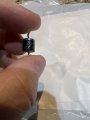
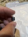
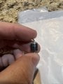
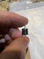
I could potentially use my 12vDC to 300Vdc circuit to make the upper circuit… then I just need to construct the lower portion…This is what i made up as a replacement CDI system for an engine.View attachment 275575View attachment 275576
That looks like the ignition coil? I was asking about the trigger coil.Confirmed. Coil (-) terminal has a jumper to casing.

My apologies.That looks like the ignition coil? I was asking about the trigger coil.
I've been musing over making a more sensitive trigger circuit and offer the following one. It uses one comparator of an LM339 quad comparator chip for sensing the initial negative-going half cycle of the trigger coil (so coil polarity matters). With the components shown a ~20mV signal can be enough to trigger things, but adding series resistance to the trigger coil can reduce sensitivity if required. High sensitivity requires shielded cable from the coil to the electronics.
I can't bear to see things going to waste, so pressed the other 3 comparators into use for the timing functions. No 555s !
Q1 drives the SCR gate.
The R4C2 time constant sets the width of the enable/disable window.
The R6C3 time constant sets the delay before the SCRgate pulse starts.
Total current draw for the circuit shown averages less than 2mA, so that shouldn't flatten your battery too quickly!
View attachment 275623

Uh wow!That looks like the ignition coil? I was asking about the trigger coil.
I've been musing over making a more sensitive trigger circuit and offer the following one. It uses one comparator of an LM339 quad comparator chip for sensing the initial negative-going half cycle of the trigger coil (so coil polarity matters). With the components shown a ~20mV signal can be enough to trigger things, but adding series resistance to the trigger coil can reduce sensitivity if required. High sensitivity requires shielded cable from the coil to the electronics.
I can't bear to see things going to waste, so pressed the other 3 comparators into use for the timing functions. No 555s !
Q1 drives the SCR gate.
The R4C2 time constant sets the width of the enable/disable window.
The R6C3 time constant sets the delay before the SCRgate pulse starts.
Total current draw for the circuit shown averages less than 2mA, so that shouldn't flatten your battery too quickly!
View attachment 275623
here is a scope picture of the Trigger coil at start speed… the at 500 rpmThat looks like the ignition coil? I was asking about the trigger coil.
I've been musing over making a more sensitive trigger circuit and offer the following one. It uses one comparator of an LM339 quad comparator chip for sensing the initial negative-going half cycle of the trigger coil (so coil polarity matters). With the components shown a ~20mV signal can be enough to trigger things, but adding series resistance to the trigger coil can reduce sensitivity if required. High sensitivity requires shielded cable from the coil to the electronics.
I can't bear to see things going to waste, so pressed the other 3 comparators into use for the timing functions. No 555s !
Q1 drives the SCR gate.
The R4C2 time constant sets the width of the enable/disable window.
The R6C3 time constant sets the delay before the SCRgate pulse starts.
Total current draw for the circuit shown averages less than 2mA, so that shouldn't flatten your battery too quickly!
View attachment 275623


It's the LTspice simulation file, for anyone that wants to play with the circuit.What is that file attached?
An inverter-generator runs at 3000 rpm or 3600rpm. The output of the sensor shown in post #166 would, of course, be much lower at the OP's 425rpm, so might not be enough to trigger the average SCR.This is all thats needed to trigger the SCR in the circuit i posted.
thencrappy little circuit I started with was able to be triggered by the coil. However it was powered by the wall wart and had internal characteristics that allowed the scr to shut off and fire again.An inverter-generator runs at 3000 rpm or 3600rpm. The output of the sensor shown in post #166 would, of course, be much lower at the OP's 425rpm, so might not be enough to trigger the average SCR.

