Odd supply for an op amp?

Thread Starter

Homebrew1964

Joined Nov 22, 2024
232
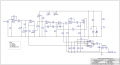
I just built this circuit that has a CA3080 op amp at the output, i understand this device isn't a regular op amp but i always thought chips needed a positive and a 0V or negative on the other supply pin, i havn't measured whats on pin 4 in this circuit but clearly it doesn't go to 0V or negative, the data sheet states a 0V supply.

Just curious since the circuit is working fine.
 

Attachments

dl324

Joined Mar 30, 2015
18,360
i havn't measured whats on pin 4 in this circuit but clearly it doesn't go to 0V or negative, the data sheet states a 0V supply.
There's nothing that says the positive and negative supplies for an opamp need to be the highest and lowest voltages in the circuit.

There's a voltage divider on the V- pin. It's at 1.62V.
 

WBahn

Joined Mar 31, 2012
32,919
There's nothing that says the positive and negative supplies for an opamp need to be the highest and lowest voltages in the circuit.

There's a voltage divider on the V- pin. It's at 1.62V.
But the two questions that come to my mind are:

What is the purpose of having the negative supply elevated?

What is the purpose of powering the opamp with a supply having well over 1 kΩ of resistance?

Assuming it's not a mistake, I have to assume that it's some kludged-up distortion effect.
 

dl324

Joined Mar 30, 2015
18,360
Assuming it's not a mistake, I have to assume that it's some kludged-up distortion effect.
There's so much wrong with that schematic (for instance, using a box instead of an opamp symbol for the CA3080), that I'm not inclined to try to analyze it.

There's a weak virtual ground formed by R14 and R15, so the V- voltage would allow the output to just about get down to the virtual ground voltage.
 

WBahn

Joined Mar 31, 2012
32,919
There's so much wrong with that schematic (for instance, using a box instead of an opamp symbol for the CA3080), that I'm not inclined to try to analyze it.
I'm not going to get bent over someone using the symbol that the simulator provides instead of taking the time to make their own, which likely involves learning how to create symbols and tie them to the device model.
 

Thread Starter

Homebrew1964

Joined Nov 22, 2024
232
There's so much wrong with that schematic (for instance, using a box instead of an opamp symbol for the CA3080), that I'm not inclined to try to analyze it.

There's a weak virtual ground formed by R14 and R15, so the V- voltage would allow the output to just about get down to the virtual ground voltage.
All i can tell you is that despite any wrongs in the schematic, the circuit works very well and does exactly what i wanted

thanks for the replies everyone.
 

WBahn

Joined Mar 31, 2012
32,919
All i can tell you is that despite any wrongs in the schematic, the circuit works very well and does exactly what i wanted

thanks for the replies everyone.
Try connecting the negative supply of the opamp to the negative power supply rail and see if it actually makes a significant difference.
 

Thread Starter

Homebrew1964

Joined Nov 22, 2024
232
Try connecting the negative supply of the opamp to the negative power supply rail and see if it actually makes a significant difference.
My circuit isn't on breadboard, it's laid out on veroboard and since it's working well i'm not going to mess with it... time to fit it in a box me thinks :)
 

dl324

Joined Mar 30, 2015
18,360
All i can tell you is that despite any wrongs in the schematic, the circuit works very well and does exactly what i wanted
The problem is that uA741 and CA3080 don't have much headroom when operating from 9V (4.5V/-4.5V). They're only guaranteed to get within 3V of the supplies. MC3403 isn't much better. It can go to the negative supply, but only within 2V from the positive rail. Maybe the intent is to have distortion.

The schematic would be a bit cleaner if some/all of the IC2 opamps were flipped WRT the X-axis.
 

Thread Starter

Homebrew1964

Joined Nov 22, 2024
232
The problem is that uA741 and CA3080 don't have much headroom when operating from 9V (4.5V/-4.5V). They're only guaranteed to get within 3V of the supplies. MC3403 isn't much better. It can go to the negative supply, but only within 2V from the positive rail. Maybe the intent is to have distortion.
There is absolutely no distortion, the output is a clean square wave. It sounds great
 
Top