Power supply with LM317 Advices needed.

Thread Starter

jm-X

Joined Feb 12, 2023
24
Hi all,

I found this schematic from a well known AAC member.
Thanks to him, it seems it's K C.

Thanks you also for your previous replies....
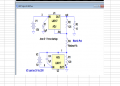

PSU-LM317-Initial-Schematic.png

I added a few components, and as usual, would be nice if you could give your advices.

Are 2 x 4700 µF polarised capacitors needed - filtering of course - and need for another 100 µF after the two previous?

Location: B3

I think i made a mistake:

In the initial schematic, R3 15 Ohm, was the load; so i have to remove it in this one?

Location: B5 Top right.
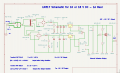
10V-18V-DC-PSU-Schematic.png

Question 1:
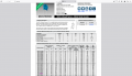
I add a varistor MOV14D741K RMS 300 V 385 V DC
Location: B1 Top Left after fuse holder.
Usefull or useless?

See Datasheet in attached files.

Question 2:
My main concern is to get 10 V DC Max Output 1 A , in order to avoid frying my brushless drive...

With a "No-Load" 50 V transfo and 2 x 1.25 A and 12 V, i got the right item?

18V DC is less important because i can get it with and LM350 by example.

So is TIP122 a good answer or not?

About TIP122 : with 1.82 V at Base, minus 1.4 V - Darlington pair - so 0.4 V cut-off state, I guess?
Right or wrong?

11 V DC : 2 V DC TIP122 Base minus 1.4 V=0.6 V

12 V DC : 2.18 V DC TIP122 Base minus 1.4 V = 0.66 V
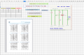
TIP122-Resistor.png

Datasheet in files attached.


Question 3:

I also tried to replace TIP122 by a Zener Diode with it's resistor.

Also to supply brushless drive with 10 V DC and 1 A Maxi, for AWG20 wire.

Good or very bad idea?
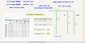

Zener-Diode-Schematic-Sheet.png

Datasheet attached.

Question 4:

It's about sending files: may i send on this forum, kicad files or spreadsheet files?


Nice day to all forum members.

Jm
 

Attachments

Maybe someone else will analyse this and answer your questions one by one, but please forgive me for asking, what result are you looking for? It looks like you just want a 10V DC supply with 1A output. You can buy a switch mode power supply which is safe and efficient for very little money. If you also want 18V consider using an old laptop charger with around 19V and 3A output - and use a LM2596 buck converter module (also very inexpensive) to provide the 10V.

Switch mode power supplies and buck converters are used in huge volumes so the technology is well developed and the volume makes them really cheap to buy. You will spend more money building something yourself. Maybe focus on building something which interests you that can't be bought?
 

AnalogKid

Joined Aug 1, 2013
12,217
That is a *lot* of parts for a single-output supply. I don't see any reason for the second LM317. The datasheet has the recommended circuit.

If you want to build one rather than buy one (which I encourage), but want to reduce your risk, there are lotsa kits available on ebay that include a pc board, input and output connectors, a heatsink, etc.

As above, what is it that you are trying to achieve?

Input voltage
Output voltages
Output currents
Adjustment ranges (if any)

Application - what is the supply powering?

ak
 

kiroma

Joined Apr 30, 2014
114
I feel (others too, it seems) that your description is lacking a bit of context. For example, what are you trying to do, besides building this power supply (what will it feed?)? Do you have a desire for efficiency? Have you thought of buying a module that does all that, as @Jerry-Hat-Trick said? Are you building this because you want to DIY for pleasure/learning?
These answers can change dramatically the course of your project.
 

AnalogKid

Joined Aug 1, 2013
12,217
The bottom regulator is for adjusting the output voltage to 0V.
It's not needed for a fixed voltage supply.
Agree about not needing it.

If the TS really wants it (or its function), you can get there with a charge pump plus an LM4040. This eliminates the second transformer secondary, bridge, fuse, and most of the massive filtering. BTW, 9400 uF seems a bit much (like 100x) for a 10 mA load.

In the TS schematic, U1 needs an output capacitor, like 47 uF or 100 uF. U2 can get by with 1 uF.

ak
 
Last edited:

Thread Starter

jm-X

Joined Feb 12, 2023
24
The bottom regulator is for adjusting the output voltage to 0V.
It's not needed for a fixed voltage supply.
Hi, crutschow,

Thanks a lot for your reply.
I agree that the bottom regulator is only for 0V output voltage.

18 V output DC will be with a LM350.
Output 1.25 to 35 V . In this case no need for 0V.

jm
 

Thread Starter

jm-X

Joined Feb 12, 2023
24
Agree about not needing it.

If the TS really wants it (or its function), you can get there with a charge pump plus an LM4040. This eliminates the second transformer secondary, bridge, fuse, and most of the massive filtering. BTW, 9400 uF seems a bit much (like 100x) for a 10 mA load.

In the TS schematic, U1 needs an output capacitor, like 47 uF or 100 uF. U2 can get by with 1 uF.

ak
Thanks a lot for your reply
 

Thread Starter

jm-X

Joined Feb 12, 2023
24
I feel (others too, it seems) that your description is lacking a bit of context. For example, what are you trying to do, besides building this power supply (what will it feed?)? Do you have a desire for efficiency? Have you thought of buying a module that does all that, as @Jerry-Hat-Trick said? Are you building this because you want to DIY for pleasure/learning?
These answers can change dramatically the course of your project.
Hi kiroma,

First thanks a lot, as others to reply.

I want only, in DIY mode, a linear power supply: 0 > 10 V DC 1A to supply my brushless drive.

Doesn't matter if efficiency is lower than Switch P S U.

No Switch Power Supply to avoid EMI and so on, on electronics of the boards; and also more difficult to build!!!!

Also for the same brushless drive, i only need 18 V DC : so a classic circuit with LM350.

Nice day.

jm
 

Thread Starter

jm-X

Joined Feb 12, 2023
24
That is a *lot* of parts for a single-output supply. I don't see any reason for the second LM317. The datasheet has the recommended circuit.

If you want to build one rather than buy one (which I encourage), but want to reduce your risk, there are lotsa kits available on ebay that include a pc board, input and output connectors, a heatsink, etc.

As above, what is it that you are trying to achieve?

Input voltage
Output voltages
Output currents
Adjustment ranges (if any)

Application - what is the supply powering?

ak
Hi AnalogKid,

Thanks a lot for your reply.
Input voltage : (12*1.414)-1.4 = 15.568 after Bridge Rectifier

Output voltage: 0 > 10 V DC for a brushless drive

Output current: 1 A due to AWG20

Adjustment range: 0 > 10 V DC as stated above

Application: as above Brushless drive

Nice day.

jm
 

Thread Starter

jm-X

Joined Feb 12, 2023
24
Maybe someone else will analyse this and answer your questions one by one, but please forgive me for asking, what result are you looking for? It looks like you just want a 10V DC supply with 1A output. You can buy a switch mode power supply which is safe and efficient for very little money. If you also want 18V consider using an old laptop charger with around 19V and 3A output - and use a LM2596 buck converter module (also very inexpensive) to provide the 10V.

Switch mode power supplies and buck converters are used in huge volumes so the technology is well developed and the volume makes them really cheap to buy. You will spend more money building something yourself. Maybe focus on building something which interests you that can't be bought?
Hi Jerry-Hat-Trick,

Thanks a lot for your reply, first.

I want DIY this power supply, rather to buy something " on the shelf ".

And yes, my interest is building something that can't be bought!

Nice day.

jm
 
Power supplies should be, and most times are, a beginner’s first projects.

So I encourage you to build one, Godspeed in your project, but go slow. There are many, many circuits on the WWW that have several and severe problems.
Build the circuit from a reliable source, I. E. a datasheet from one the major semiconductor players. Bonus points if you can find the National Semiconductor’s LM317 datasheet.
 
I want DIY this power supply, rather to buy something " on the shelf ".
Whilst I’d always urge someone with limited experience not to build anything that plugs into the mains, a power supply using a transformer is relatively safe

For a DC supply variable up to 10V with 1A current a minimal design would need a transformer and bridge rectifier as you describe, followed by a large capacitor to reduce ripple followed by a linear regulator like the LM317, a resistor and a potentiometer.

Are you confident to calculate the necessary transformer ratio, the value of the capacitor needed to ensure sufficient headroom for the LM317 through the cycle at 10V and 1A, and suitable values for the resistor and potentiometer?

At low voltage output the LM317 will get hot, you’ll need a heatsink.
 

Thread Starter

jm-X

Joined Feb 12, 2023
24
Hi Jerry-Hat-Trick,

Necessary transformer ratio: no problem as i bought some toroidal transformers, and they work fine...

About capacitor:

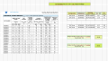
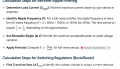
Formulas.png


About Heatsink, my spreadsheet is helpfull for Thermal Junction, Ambiant and Case Coefficients and so on, with derating to stay in Safe Operation Area....
Got also thermal paste and isolator for T03 and T220 components.

I build 20 years ago a basic PSU, with LM350 or an other part, and still works, but of course no 0 V DC output:(


Potentiometer: see below.

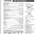
Bournes-Datasheet.png


But about resistors values for TIP122 - if it's a good or bad idea ? - really, i think i'm going to test in a breadboard, and adjust with tolerance of components...

About Power: 0.6 W Resistor as Ib for TIP122 is 0.12 A Maxi.

Say: 12 / (R4+R5) = 24*10^-3 Ib for R4 and R5 ( See my basic schematic )
P = R* I² = 0,0288 W

If i'm wrong - and for TIP122 choice and also formula - you can tell it.

TIP122-Datasheet-Mini.png


My two main concerns, are:

Not frying my costly brushless drive!!!

To get an output of 0 V DC to Maxi 10 V DC; of course, if I supply my BLDC with reference voltage like 1.25 V DC, I doubt it will stop !!!!
AWG 20 so 1 A
:):):)


Thanks a lot for your reply, it's positive as i like in this forum.

Nice day for you and all AAC Forum members.

Jm
 

Thread Starter

jm-X

Joined Feb 12, 2023
24
Power supplies should be, and most times are, a beginner’s first projects.

So I encourage you to build one, Godspeed in your project, but go slow. There are many, many circuits on the WWW that have several and severe problems.
Build the circuit from a reliable source, I. E. a datasheet from one the major semiconductor players. Bonus points if you can find the National Semiconductor’s LM317 datasheet.
Hi Schmitt trigger,

Thanks for your positive reply.
Nice day.

Jm
 
If having an output which can be adjusted to 0V is important to you then maybe select values for the adjustment resistor and potentiometer which provide an output from say 11.2V and 1.25V and put two diodes in series to drop the output voltage. This will work if you can live with small changes in voltage with current and is much simpler than the two LM317 solution
 

AnalogKid

Joined Aug 1, 2013
12,217
This will work if you can live with small changes in voltage with current
Plus changes in voltage with changes in ambient air temperature, and changes in component temperature. In round numbers, it reduces the quality of the regulation to that of a single zener diode.

It also increases the output impedance, which is the source impedance seen by the load. This will affect both mechanical and electrical damping.

and is much simpler than the two LM317 solution
Not really. It's 4 pins versus 5 pins.

ak
 

Thread Starter

jm-X

Joined Feb 12, 2023
24
If having an output which can be adjusted to 0V is important to you then maybe select values for the adjustment resistor and potentiometer which provide an output from say 11.2V and 1.25V and put two diodes in series to drop the output voltage. This will work if you can live with small changes in voltage with current and is much simpler than the two LM317 solution
Hi Jerry-Hat-Trick,

Thanks a lot for your help.

I think i'm going to do some breadboard electronic circuit, before drawing with Kicad.

Vf is function of If ....

Nice day.

jm
 
Top