Facebook
 Google
 GitHub
 Linkedin
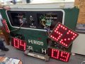
Here is where we are now. Things are looking good!!!
https://drive.google.com/file/d/11m8PAILpt9GAOd5BD-XXxjCPT5Xw9FDC/view?usp=sharing
https://drive.google.com/file/d/11m8PAILpt9GAOd5BD-XXxjCPT5Xw9FDC/view?usp=sharing
| Thread starter | Similar threads | Forum | Replies | Date |
|---|---|---|---|---|
| D | Running Low-Ohm Meter circuit in parallel | Test & Measurement | 19 | |
| A | Basic Electrical question problem (resistor network) | Homework Help | 10 | |
| E | Voltage regulator question | Power Electronics | 18 | |
| Y | smith chart logical problem question | Wireless & RF Design | 0 | |
|
|
Problem with Electrical Circuit Question | Homework Help | 8 |