 Facebook
 Google
 GitHub
 Linkedin
Hello everyone
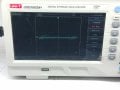
I've tried this simple curve tracer with my oscilliscope in the attached photo
And the circuit in the attached screenshot screenshot
, attached the oscilloscope manual also
It worked fine, and helped me in testing circuits and find fault, but my question why so much noise?, I've seen similar on YouTube, without all this noise you see at the photo of my scope
Do I miss something?, or it's the scope I use?, by the way I've tried different scale settings but that's the best I got
Anyone got similar issue?, is it possible to make it better?
Attachments
-
 1.8 MB Views: 39
 -
2.6 MB Views: 27
-
 462.8 KB Views: 40


