Facebook
 Google
 GitHub
 Linkedin
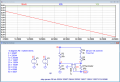
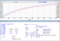
Thanks a lot,You set the value of the U2 pot plus R3 equal to the thermistor resistance at the minimum temperature of -5°C (for simulation purposes you can eliminate U2 and just use R3).
That will give 0V out @ -5 degrees.
Then you select a bridge voltage, Vb, to give the maximum output voltage you want at the +35°C resistance (formula given in post #31).
I will try the same and let you know results.
I got overwhelming support for this thread.
Thank you all !!!