Facebook
 Google
 GitHub
 Linkedin
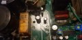
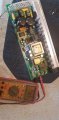
Actually it is a little better than I thought, it is the Promariner 1240i plus version, which does Battery Balance Control individually.
The ProTech-i Series battery charger incorporates industry leading technology, delivering fully automatic and
Sequential Multi-Stage Charging that provides electronically controlled charging, conditioning and
maintenance of all batteries and or banks connected.
High Line Features:
Automatic Wide Range / Global AC input 95 - 250VAC
Active Battery Balance Control (BBC) monitors charging while conditioning and extending
battery life ensuring that no battery is ever overcharged (1230i Plus, 1240i Plus & 2420i Plus only)
User Programmable Absorption / Conditioning Mode: 1, 2, 3, or 4 hours.
User Programmable Battery Type / Charge Profile Selector- 3 Settings:
Out of Box Factory / User Setting 1 : Flooded (Lead-acid)
User Setting 2 : AGM
User Setting 3 : GEL
Standard Features:
Advanced Electronic Technology yielding a heavy duty stylish and compact On-Board Marine Charger.
Expanded LED Operation Status Center Includes High Visibility LED's for:
Fast Charge, Absorption, Float, and Discrete Battery Type LED indicators for: Flooded, AGM and GEL Batteries.
Fully Automatic & Sequential Multi-Stage Charging (example below is for a 12 Volt ProTech -i model)
Factory set out of the box for Flooded (Lead-acid) battery (s).
Sequential Multi-Stage Battery Charging
Stage 1 Fast Charge = Maximum Amperage Output until Battery (s) reach 14.7 VDC
Stage 2Absorption Charge / Conditioning Mode = Precision 14.7 VDC to Fully Charge & Desulfate Battery(s).
Stage 3 Float / Maintenance/ Ready Mode= Precision Finishing & maintaince Voltage of 13.5VDC
Stage 4 Recycle / Dockside Power = If while docked and connected to shore power your Batteries have
a continuous excessive DC load for lighting, entertainment, or appliances, etc. The ProTech-i Series will
return to Mode 1 providing your batteries up to the full amperage rating of the charger to meet the demand
of the load and begin charging your battery (s).
The ProTech-i Series battery charger incorporates industry leading technology, delivering fully automatic and
Sequential Multi-Stage Charging that provides electronically controlled charging, conditioning and
maintenance of all batteries and or banks connected.
High Line Features:
Automatic Wide Range / Global AC input 95 - 250VAC
Active Battery Balance Control (BBC) monitors charging while conditioning and extending
battery life ensuring that no battery is ever overcharged (1230i Plus, 1240i Plus & 2420i Plus only)
User Programmable Absorption / Conditioning Mode: 1, 2, 3, or 4 hours.
User Programmable Battery Type / Charge Profile Selector- 3 Settings:
Out of Box Factory / User Setting 1 : Flooded (Lead-acid)
User Setting 2 : AGM
User Setting 3 : GEL
Standard Features:
Advanced Electronic Technology yielding a heavy duty stylish and compact On-Board Marine Charger.
Expanded LED Operation Status Center Includes High Visibility LED's for:
Fast Charge, Absorption, Float, and Discrete Battery Type LED indicators for: Flooded, AGM and GEL Batteries.
Fully Automatic & Sequential Multi-Stage Charging (example below is for a 12 Volt ProTech -i model)
Factory set out of the box for Flooded (Lead-acid) battery (s).
Sequential Multi-Stage Battery Charging
Stage 1 Fast Charge = Maximum Amperage Output until Battery (s) reach 14.7 VDC
Stage 2Absorption Charge / Conditioning Mode = Precision 14.7 VDC to Fully Charge & Desulfate Battery(s).
Stage 3 Float / Maintenance/ Ready Mode= Precision Finishing & maintaince Voltage of 13.5VDC
Stage 4 Recycle / Dockside Power = If while docked and connected to shore power your Batteries have
a continuous excessive DC load for lighting, entertainment, or appliances, etc. The ProTech-i Series will
return to Mode 1 providing your batteries up to the full amperage rating of the charger to meet the demand
of the load and begin charging your battery (s).