Noise on PSU and opamp

Thread Starter

DPJ

Joined Mar 1, 2019
5
Hi

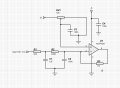
I have been trying to amplify a small signal (1 mV) with an opamp . I noticed on all of my power supply I get something like 100uV volts of slow movement. I try to amplify my small 1 mV signal by 5 and the 100uV noise becomes 500uV

Can somebody please help me either with suggestions on quieting the power supply or a better amplifying circuit on the opamp to ignore the noise as I am at a loss what to do about this any ideas would be greatly appreciated?

Thank You
David
 

danadak

Joined Mar 10, 2018
4,057
Last edited:

Audioguru

Joined Dec 20, 2007
11,248
Some opamps produce lots of noise but audio opamps produce low noise levels.

Most opamps have an excellent power supply noise rejection ratio of 100,000 times or more at low frequencies, except for the lousy old LM324 and LM358 it could be as low as 2000 times.

Which opamp are you using?
 

Thread Starter

DPJ

Joined Mar 1, 2019
5
Hi

Thanks for your response.
I am using a MCP6041 low current and looking at a frequency below 5 Hz

Regards
David
 

Hymie

Joined Mar 30, 2018
1,347
From you last post, is the noise you are experience at 5Hz, or is the signal you are processing at a nominal 5Hz?

If you are trying to amplify EEG signals, then the recommended input impedance (at the op-amp) should be somewhere between 100Ω and 5kΩ.
 

Audioguru

Joined Dec 20, 2007
11,248
The low current MCP6041 opamp is very noisy and its power supply noise rejection ratio is not good and has no minimum value.
 

TeeKay6

Joined Apr 20, 2019
573
The low current MCP6041 opamp is very noisy and its power supply noise rejection ratio is not good and has no minimum value.
@Audioguru
A minor comment. My Microchip datasheet for the MCP6041 does show a min "power supply rejection" of 70db. No maximum is given or expected. Otherwise, I agree that the MCP6041 may not be a good choice for this application although we do not yet know the source of the "noise" the TS complains of.
 

Audioguru

Joined Dec 20, 2007
11,248
Your capacitor C2 does almost nothing because it is connected to "the virtual ground" inverting input of the opamp that has no signal voltage.
If you want the opamp to have gain and double filters then it should be non-inverting.
 

TeeKay6

Joined Apr 20, 2019
573
Your capacitor C2 does almost nothing because it is connected to "the virtual ground" inverting input of the opamp that has no signal voltage.
If you want the opamp to have gain and double filters then it should be non-inverting.
Your capacitor C2 does almost nothing because it is connected to "the virtual ground" inverting input of the opamp that has no signal voltage.
If you want the opamp to have gain and double filters then it should be non-inverting.
Some or all of the filtering could be moved to the feedback (i.e. around R3), but the filtering shown is unlikely to have much effect for a low frequency signal. (Yes, it would help to see an image of the "noise" on the PS and at the output of U1.)

The TS says that he sees a low frequency variation (construed in comments to be "noise") on +5V, amplitude of variation about 100uV. Further, he says that same variation, amplified by U1 (Av=5) to 500uV, at the output of U1. As @to3metalcan has suggested, the "noisy" 5V is used as reference to provide offsetting; thus, whatever low frequency variation is in the 5V passes more or less directly into the + input of the amplifier...and is thus amplified (X6). One solution would be to provide a more stable reference that does not show the slow variation of the 5V.
 

to3metalcan

Joined Jul 20, 2014
263
I'm not sure why you're using a variable resistor for DC bias. Unless you can give a good reason why you might need to adjust the DC bias to a value other than 1/2 the supply voltage, just use two equal resistors. The bypassing cap you've shown (C3) isn't NEARLY big enough. The lower frequency the signals handled, the bigger that cap needs to be. For details, you can read the TI app note that @ronv posted.

@Audioguru is also correct in saying that C2 isn't doing what I think you want it to do...if it's doing anything, it's probably making the op amp a bit unstable. You'll either need to add another series resistor after it or trade it for a capacitor in the feedback loop across R3.
 

Thread Starter

DPJ

Joined Mar 1, 2019
5
Thanks for all your help, Can anyone recommend a very low current op amp with better noise characteristics

Thank You
 

ebeowulf17

Joined Aug 12, 2014
3,307
Thanks for all your help, Can anyone recommend a very low current op amp with better noise characteristics

Thank You
I don't think you're seeing op amp noise at all. I think you're seeing power supply variations because you're feeding the power supply (through a voltage divider) into one of your op amp inputs. Your problem isn't op amp stability, it's reference voltage stability. If you feed that unstable reference into ANY op amp, you'll still get an unstable output.

What you need is a more stable source for your offset/reference voltage. If you want a less noisy op amp, that's fine too, but that won't address the problem described in this thread.

Thanks to @TeeKay6 for pointing it out:
As @to3metalcan has suggested, the "noisy" 5V is used as reference to provide offsetting; thus, whatever low frequency variation is in the 5V passes more or less directly into the + input of the amplifier...and is thus amplified (X6). One solution would be to provide a more stable reference that does not show the slow variation of the 5V.
 

ronv

Joined Nov 12, 2008
3,770
Thanks for all your help, Can anyone recommend a very low current op amp with better noise characteristics

Thank You
If your stuck with that configuration you can build a little precision regulator like a TL431 for the reference voltage.
It you can't stand any DC offset you may need to set it to 3 volts or so and the adjust it for zero offset.
upload_2019-7-19_21-34-27.png

If you can tell us more about what you are doing we can probably help more.
 

Thread Starter

DPJ

Joined Mar 1, 2019
5
Hi

I am trying to make a sensitive phase detector I am inputting 2 x 5 Khz signals into a SA612 this device does have a differential output but I am only using one output this is then 10 Khz after the mixer I am then low passing to about 5 herts and the other circuit you already have my problem is there is only about 1mv per 1 degree(of shift) I an trying to get this up so I can see .1 degree of movement or more.

Thanks for your help
 
Top