Noise in twisted shielded pair (TSP)

Thread Starter

cadetali007

Joined Apr 19, 2025
9
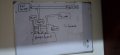
I have 03 different pairs of shielding twisted cable (STP) all going side by side and are connected to an LRU. 02 pairs are of input while one pair is of output from LRU. Pair 1 has power supply of 5v and ground. Pair 2 has voltage input in mv with ground. Pair 3 which is the output pair has 03 wires which are of ground and 02 wires of voltage in mv. Shielding of all 03 pairs are grounded with each other and then one wire is grounded to a single point. I am having noise on 3rd pair. What can induce that noise.
 

Thread Starter

cadetali007

Joined Apr 19, 2025
9
Actually, aircraft engine exhaust gas temperature which is measured by the thermocouples is converted into mv. These signals are tapped for recording. These small signals are supplied to an amplifier using STP. However, exhaust gas temperature is fluctuating in recording at higher rpm but it is fine at lower rpm. At high rpm there are very high fluctuations. It was problem in one of the aircraft and i just pressed the end towards the amplifier and the problem was resolved. I thought it was grounding problem which got rectified. Using previous technique, i tried same but noise is still there. Later i saw that insulation was slightly peeled off of STP and i wonder whether this can be a problem. I have an oscilloscope but i don't know how to use it to analyze and identify noise contributer.
 

KeithWalker

Joined Jul 10, 2017
3,604
What is "STP"? Standard temperature and pressure?
Connect the oscilloscope probe tip to the fluctuating output and the probe ground clip to circuit ground. Adjust the amplitude and sweep speed to give a stable on-screen display. Take a picture of it and post it on this thread, showing the amplitude and speed of the display.
 

Thread Starter

cadetali007

Joined Apr 19, 2025
9
Thanks for your response. STP stands for shielded twisted pair cable. I have on average 20 mv output. So what should be my time and voltage scale values please.
 

Thread Starter

cadetali007

Joined Apr 19, 2025
9
What is "STP"? Standard temperature and pressure?
Connect the oscilloscope probe tip to the fluctuating output and the probe ground clip to circuit ground. Adjust the amplitude and sweep speed to give a stable on-screen display. Take a picture of it and post it on this thread, showing the amplitude and speed of the display.
Thankyou for your reply. Actually i can only connect oscilloscope with aircraft engine switched off. Is it necessary for the signal to be there or even without any signal, i can see noise by shaking suspected wires.
 

KeithWalker

Joined Jul 10, 2017
3,604
Start with a vertical sensitivity of 5mV per division. Adjust if necessary. The horizontal sweep speed will depend on the nature of the noise interference. With triggering set to "Auto", start with a sweep speed of 100mS/div. Gradually decrease the time/div until you get something that looks like the noise that you are experiencing. Double check the results by looking at the output of a good unit, using the same settings.
 

Thread Starter

cadetali007

Joined Apr 19, 2025
9
Start with a vertical sensitivity of 5mV per division. Adjust if necessary. The horizontal sweep speed will depend on the nature of the noise interference. With triggering set to "Auto", start with a sweep speed of 100mS/div. Gradually decrease the time/div until you get something that looks like the noise that you are experiencing. Double check the results by looking at the output of a good unit, using the same settings.
Its really really helpful tbh. I am very thankful for such an excellent response. I will check it on monday and let you know, please. Actually there are 03 separate shielded twisted pairs routed together to amplifier. I found shield insulation of all 03 pairs slightly peeled off exposing shield at single points, but i think it shouldn't be issue as shielding is intact. Furthermore, Their shielding is grounded with each other in triangulation and 01 grounding is ground to aircraft. I also found 01 grounding wire between 02 twisted pair damaged at a single point. I am not sure whether or not it can be a issue. So i will simply check with oscilloscope.
 

LowQCab

Joined Nov 6, 2012
5,101
This may simply come down to a Harness routing problem.
Anything coming close to the Magneto(s), or anything connected to the Magneto(s)
can overwhelm any type of Shielding.
Distance is required.
.
.
.
 

Thread Starter

cadetali007

Joined Apr 19, 2025
9
This may simply come down to a Harness routing problem.
Anything coming close to the Magneto(s), or anything connected to the Magneto(s)
can overwhelm any type of Shielding.
Distance is required.
.
.
.
It was working perfectly fine for years with similar routing.
 

MisterBill2

Joined Jan 23, 2018
27,314
If any accuracy is required then connecting thermocouple wires must be continued in the correct thermocouple wire type. And I have no clue as to what an "LRU" might be.
 

KeithWalker

Joined Jul 10, 2017
3,604
If any accuracy is required then connecting thermocouple wires must be continued in the correct thermocouple wire type. And I have no clue as to what an "LRU" might be.
An LRU is a line replaceable unit. See post #3 for more details. This is a standard telemetry installation in plane. The wiring is of the correct type. It is designed correctly. One unit is giving intermittent results. That is why it is being investigated.
 

KeithWalker

Joined Jul 10, 2017
3,604
Its really really helpful tbh. I am very thankful for such an excellent response. I will check it on monday and let you know, please. Actually there are 03 separate shielded twisted pairs routed together to amplifier. I found shield insulation of all 03 pairs slightly peeled off exposing shield at single points, but i think it shouldn't be issue as shielding is intact. Furthermore, Their shielding is grounded with each other in triangulation and 01 grounding is ground to aircraft. I also found 01 grounding wire between 02 twisted pair damaged at a single point. I am not sure whether or not it can be a issue. So i will simply check with oscilloscope.
How are the cables connected to the amplifier unit? If moving the cables around causes a step function in the output (visible on the scope), I would suspect intermittent terminal blocks or connectors if they are used
 

Externet

Joined Nov 29, 2005
2,628
Or, the signal source fed to the STP became noisy itself, or the LRU became noisy and is backfeeding it into the STP. First follow the 'shaking' anomaly.
 

MisterBill2

Joined Jan 23, 2018
27,314
Not only is a noisy source possible, if the shield has become connected to "ground" at a high noise voltage/current point, noise can be coupled into the shield. THAT was a very stubborn problem in one machine. The solution was to completely isolate the transducer housing from the "grounded" mounting hardware. Totally non-intuitive, but that was the cure. THAT was a strain-gage bridge sensor pressure transducer, testing a motor/pump assembly driven by a noisy DC brushed motor.
BLDC motors were not yet commonly available, back in 1977.
 

Thread Starter

cadetali007

Joined Apr 19, 2025
9
Not only is a noisy source possible, if the shield has become connected to "ground" at a high noise voltage/current point, noise can be coupled into the shield. THAT was a very stubborn problem in one machine. The solution was to completely isolate the transducer housing from the "grounded" mounting hardware. Totally non-intuitive, but that was the cure. THAT was a strain-gage bridge sensor pressure transducer, testing a motor/pump assembly driven by a noisy DC brushed motor.
BLDC motors were not yet commonly available, back in 1977.
Thanks for your reply but i couldn't really understand the point but i am attaching the circuit drawn on board.
 

Attachments

MisterBill2

Joined Jan 23, 2018
27,314
What that drawing shows is a whole lot of signal return paths tied to "grounds". OR POSSIBLY THEY ARE NOT TIED TO MULTIPLE GROUNDS. OR are all of the "grounded" connections actually shields?? The shield of a twisted pair that has one side at "Ground potential " needs attention to just where it is connected.
 

KeithWalker

Joined Jul 10, 2017
3,604
What that drawing shows is a whole lot of signal return paths tied to "grounds". OR POSSIBLY THEY ARE NOT TIED TO MULTIPLE GROUNDS. OR are all of the "grounded" connections actually shields?? The shield of a twisted pair that has one side at "Ground potential " needs attention to just where it is connected.
The TS is not asking how to modify the installation. It is a standard well tried and tested piece of instrumentation installed on many planes. He is asking advice on how to trouble shoot a faulty one.
 

MisterBill2

Joined Jan 23, 2018
27,314
Post #18 includes a suggestion on what may be a problem.
GIVEN that the fix does not appear to have been found, it seems that something being different from the exact scheme that is claimed to perform correctly seems like a logical suspect. Thus my comment. I was not suggesting a re-design, but rather describing conditions that I have seen cause problems elsewhere in the past. That might require a modification of something that is not the same as what worked in the past.
So the problem is quite possibly something having become different from what it should be. Quite often that requires a detailed understanding of just exactly how things were when they were functioning correctly. Thus the question as to what is different.

Post #16 describes what appears to be a similar problem that I experienced, and what actually was the solution in that case. What is not clear so far is at which points all of those conductors which are stated to be at ground potential are physically tied to "external ground". An accidental connection of a "grounded wire" to the external ground at a noisy location can certainly bring noise inside the system. That condition is often a challenge to locate.

What we are not told is if this is an existing system that has suddenly developed a problem, or a new system in the process of "startup and verification." That matters! So I AM GUESSING that this is not a new design, but one assembly built to the same design, that has a problem not experienced previously. That has happened to many of us who have created designs that went into production. One system fails to perform the correct way, unlike those produced before. So the question becomes "What is different??" That is what my suggestions were about.
 
Last edited:
Top