newbie, sort of, help with a control circuit

Thread Starter

satanelec

Joined Oct 13, 2018
8
Hello all, I am trying to control a 110vdc RGB led strip with a 12vdc RGB led wifi controllers output. I have the 110vdc led controller, but I would like the features on the 12vdc controller, like wifi control, not bluetooth and the music control is better than the 110vcd controller. So I would like to take the 12vdc controllers RGB outputs and put it thru 3 mosfets for RGB on the 110vdc led strip using the 110vdc from the 110vdc controller, kind of like using an ssr, but would still like to fade and such. i have tried but failed by blowing out the mosfets i have for testing. Any ideas or schematic would be much appreciated. I have a basic knowledge of electronics, just haven't used it in YEARS.

Thanks again.
Ben
 

crutschow

Joined Mar 14, 2008
38,576
Do you have an oscilloscope so you can see how the 12V unit does the fade signal?

You can't use a triac or thyristor (SCR) with DC.
They only work with AC.
 

Thread Starter

satanelec

Joined Oct 13, 2018
8
No I do not have an oscilloscope, funny I looked up the controllers output components a they are using thyristors, at least according to the component numbers.
 

crutschow

Joined Mar 14, 2008
38,576
Okay, but you want to interface the output of the 12V controller to the 110V controller.
So it's the output of the 12V controller that's of interest.
Without knowing the nature of that output, a good interface to the 110V unit cannot be readily designed.

The output of the 110V controller is likely controlling the internal AC with thyristors to generate the output 110Vdc.
 

Thread Starter

satanelec

Joined Oct 13, 2018
8
Okay, but you want to interface the output of the 12V controller to the 110V controller.
So it's the output of the 12V controller that's of interest.
Without knowing the nature of that output, a good interface to the 110V unit cannot be readily designed.

The output of the 110V controller is likely controlling the internal AC with thyristors to generate the output 110Vdc.
Ok, makes sense, it looks like the output of the 12v controller is mosfet and voltage, while testing it was 0 to 12v. So another question would be, can a circuit be built off of the output of the 12v controller to control the 110v led strip. In other words instead of connecting a 12v led strip to the 12v controller I connect the circuit, then the 110v led strip?
 

crutschow

Joined Mar 14, 2008
38,576
Ok, makes sense, it looks like the output of the 12v controller is mosfet and voltage, while testing it was 0 to 12v. So another question would be, can a circuit be built off of the output of the 12v controller to control the 110v led strip. In other words instead of connecting a 12v led strip to the 12v controller I connect the circuit, then the 110v led strip?
Without knowing more about how the controllers operate I don't offhand see how.
The 110V controller has no inputs to control the output other then by the remote.
 

Reloadron

Joined Jan 15, 2015
7,893
I am going to venture a guess here and purely a guess. Your existing 120 volt controller using thyristors is likely based on the design of what was for years called a color organ. The link will provide a few dozen examples of the concept.

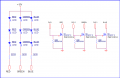
Typically I have controlled 5050 LEDs driven from a micro-controller designed for 12 volt operation using PWM and MOSFETs configured a little like the below example.
5050 LED String.png

What I do not have a solution for is how to take the typical SCR or Thyristor 120 V signal and convert it to drive a 5050 LED 12 VDC string. Anyway I figure as a guess that the 120 volt controller is likely based upon a color organ circuit as shown in the link.

Ron
 

Thread Starter

satanelec

Joined Oct 13, 2018
8
I am going to venture a guess here and purely a guess. Your existing 120 volt controller using thyristors is likely based on the design of what was for years called a color organ. The link will provide a few dozen examples of the concept.

Typically I have controlled 5050 LEDs driven from a micro-controller designed for 12 volt operation using PWM and MOSFETs configured a little like the below example.
View attachment 161492

What I do not have a solution for is how to take the typical SCR or Thyristor 120 V signal and convert it to drive a 5050 LED 12 VDC string. Anyway I figure as a guess that the 120 volt controller is likely based upon a color organ circuit as shown in the link.

Ron
Thanks, yeah the led strip is comprised of 5050 LEDs. I am actually trying to use the 12v controllers output to control a circuit to control the 110v strip. Thanks again
 
Top