Newbie PICO question

Thread Starter

bibble235

Joined May 29, 2018
57
Hi All,

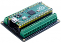
This is a really silly question and feel a fool asking it. I bought one these so when using my PICO is would be held in place and not sit on the desk with matchsticks holding it in place.
Having assembled it you can see nothing stops the PICO coming off the pins from an upward direction. And when you plug in the USB cable this does occur.

What do people do? Do they solder two pins on, glue it or something else. I have fat finger and really keen to have the things plugged in to stay plugged in. And is this the same for the green bits (sorry about the lingu) ie are they soldered underneath.

Thanks,

1661055892301.png
 

Attachments

ericgibbs

Joined Jan 29, 2010
18,766
hi 235.
First question are the Black connectors Sockets [refer to this marked up image]
If YES, then solder all the pins, on the top two rows.
I see some pins have already been soldered.

If required in the future, you can unplug the board from the Black sockets.
E

1661055892301.png
 

Ya’akov

Joined Jan 27, 2019
9,071
As @ericgibbs points out, the headers are to be soldered in place. Don't do this is you intend to use the board in some other arrangement (such as using the castellated notches next to the pins to surface mount it).

While is it possible to desolder 40 pin headers, it is no job for the neophyte and no fun even for the experienced.

One tip I will pass on is this, even with the pins properly soldered, plugging and unplugging the USB cable is fraught. The connecters loosen and can even be accidentally torn of the board after many cycles.

Instead, get a USB A male to female extension cable then plug and unplug the A end of the cable from the extension instead. This if far easier and safer.
 

ericgibbs

Joined Jan 29, 2010
18,766
hi,
I also use a Type 'A' extender/adaptor for connecting 'mini' and 'micro' USB connectors mounted on small PCB modules.

E
 

Thread Starter

bibble235

Joined May 29, 2018
57
Thanks for the replies, I thought soldering would be the answer. Rubbish at doing it do recommendation for blind fat fingered old person for purchasing one. I did it a long time ago on a far distant planet and understand there are things to consider, flux, solder and tip. In NZ so choice is restrictive.

I did buy one of these which is exactly the perfect way to use my PICO (but still want to use the other). Definitely take into consideration the USB tip. Thanks all
1661072026076.png
 

Ya’akov

Joined Jan 27, 2019
9,071
Magnification and lighting are the key to soldering connections smaller than you can easily see. This is true for SMT (Surface Mount Technology) as well as .1" THT (Through-Hole Technology) equally.

Practice, practice, and more practice will get you better at it. My particular tips on tools and supplies:

1. A temperature controlled iron set at the solder manufacturer's specs for temperature.

2. Use a ~1.5mm screwdriver style tip, no more than 2mm. I find the screwdriver shape most versatile but there are plenty of people of happily use conical tips so if that's all you can get, it will work.

3. If at all possible, run away from lead free solder. Instead, use a 63Sn/37Pb eutectic alloy solder. Note that the link is to a cheaper solder but I personally use Kester 44. Unfortunately the price has really gotten high so if you don't want to spend that, the linked one is probably fine. I can't access the NZ Amazon site from here, so I can't check to see if you can get it.

4. Get a Kester #951 no clean flux pen. This is the best flux and the pen is easiest to use. It works like a charm and makes no mess. If that's not available, choose a different no clean flux. This is important because even if you prefer to clean off the minimal white dust it leaves behind you don't have to because it is non-corrosive. Other options can eat at the traces and destroy boards in not removed.

As an aside. since the RPi Pico was deliberately designed to be .1" wider than a standard wide 40-pin IC, it will fit in a standard ZIF socket. The usual size is .6" and the Pico's pins are at .7". ZIF sockets are designed with the center being at .6" and the slots accommodating .5"—.7". This would have the advantage of easy in and out, and a secure connection when in use.
 

dl324

Joined Mar 30, 2015
16,846
I thought soldering would be the answer. Rubbish at doing it do recommendation for blind fat fingered old person for purchasing one.
Hammer headers have been invented for those who aren't able to solder:
1661104393198.png
They're expensive, but it's a bargain if you can't solder.

Another option is to buy some beer for a buddy who can solder...
 

Thread Starter

bibble235

Joined May 29, 2018
57
Magnification and lighting are the key to soldering connections smaller than you can easily see. This is true for SMT (Surface Mount Technology) as well as .1" THT (Through-Hole Technology) equally.

Practice, practice, and more practice will get you better at it. My particular tips on tools and supplies:

1. A temperature controlled iron set at the solder manufacturer's specs for temperature.

2. Use a ~1.5mm screwdriver style tip, no more than 2mm. I find the screwdriver shape most versatile but there are plenty of people of happily use conical tips so if that's all you can get, it will work.

3. If at all possible, run away from lead free solder. Instead, use a 63Sn/37Pb eutectic alloy solder. Note that the link is to a cheaper solder but I personally use Kester 44. Unfortunately the price has really gotten high so if you don't want to spend that, the linked one is probably fine. I can't access the NZ Amazon site from here, so I can't check to see if you can get it.

4. Get a Kester #951 no clean flux pen. This is the best flux and the pen is easiest to use. It works like a charm and makes no mess. If that's not available, choose a different no clean flux. This is important because even if you prefer to clean off the minimal white dust it leaves behind you don't have to because it is non-corrosive. Other options can eat at the traces and destroy boards in not removed.

As an aside. since the RPi Pico was deliberately designed to be .1" wider than a standard wide 40-pin IC, it will fit in a standard ZIF socket. The usual size is .6" and the Pico's pins are at .7". ZIF sockets are designed with the center being at .6" and the slots accommodating .5"—.7". This would have the advantage of easy in and out, and a secure connection when in use.
Thanks for the time you have put into this reply. Especially thing like zif socket. It is this kind of lingu for a beginner which is hard to google to learn. Done some work with electronics, mostly ESP32 because of my IT background but want to expand on the electronics end.
 

MisterBill2

Joined Jan 23, 2018
18,176
The right shaped tip for soldering is VITAL, otherwise there is no hope or reason to even try. But it does not have to be an expensive iron to do a good job. I have done a lot of fine pitch soldering with the cheap irons that Radio Shack used to sell for $4.95 (USD). But the tips always needed reshaping to a narrower point because they do lose material. Fortunately the solid copper tips can be filed, while the plated tips on the expensive irons must be replaced.
And certainly that lead-free solder is much more challenging to use and it always makes a lower quality connection. That is common knowledge within the industry.
 

Ya’akov

Joined Jan 27, 2019
9,071
Thanks for the time you have put into this reply. Especially thing like zif socket. It is this kind of lingu for a beginner which is hard to google to learn. Done some work with electronics, mostly ESP32 because of my IT background but want to expand on the electronics end.
I am very happy to help if I can. You will know from your experience in IT that while you have to learn the technology, that is the specifics of this or that hardware or software, you also have ot build a good background in fundamentals.

I think most people in IT didn't start with the fundamentals of computer science, rather they were attracted to, and learned about. making the technology work. But, what distinguishes the real good and successful folks who don't get left behind by inevitable changes in hardware and software is the undemanding of what lies beneath all of it.

Similarly, success in electronics depends on accumulating at least an essential set of tools for thinking about circuits and their behavior. Some things, like an intuitive understanding of Ohm's Law, and the function and behavior of basic components like resistors, capacitors, and inductors, are the difference between cargo cult engineering and building on the work of others.

I encourage you to, while you are working with MCUs, sensors, and the like, to investigate the basic behavior of circuits to start building that foundation that will let you become independently creative and have a lot more fun and satisfaction from this excellent vocation and avocation.
 
Top