Newbie needing direction on low water level alarm circuit

OK, I see the options for construction.
They are just some options that come to mind. Not sure I have the time to pick out every detail right now, but I'd be happy to look over your list.

I think these parts are tiny, so I hope proto-advantage has the required SMT to DIP adapters. So, the next concentration would be to find an appropriate adapter and order at least a few of each of the 3 parts.

and to get, sort of, comfortable with a "proto" construction. There isn't an exhaustive set of options, but there are a number of specific possibilities. I picked a huge breadboard. You might not want that.

Sometimes it's advantageous to put spacers on the PCB such that you can flip it and use it without crushing a component and depending on your worktable, you might want feet too. e.g.Foot - F-M spacer - PCB - F - F spacer - Foot This gives you a flippable PCB. If you want to include a 9V battery clip (highest component) then do so.

It used to be that nearly any component feet on a 0.1 x 0.1 INCH grid. The electronics industry has gone metric. The "breadboard" grid still seems to be 0.1 x 0.1. (2.54 mm is a metric giveaway for 0.1")

So a 1206 Resistor is IDENTICAL to a 3216 resistor. See: http://www.resistorguide.com/resistor-sizes-and-packages/

I understand using a plug in power supply for testing purposes but this presumes you already have a battery in mind that will work when it comes time to replace the power supply?
I HAD a really nice part selected to get from 9 V to 5V. This design needs a tiny bit of 5V and it makes sense to operate the buzzer on 9V. It also needs a tiny bit of 3V and 1.5V.

That part that gets you from 9V to 5V will determine battery life. The L78M05 is really simple part to use, if you want to for testing, that will get you 5V from 9V, but the battery can only be used from 9 to 7V. You need something better than that.

You can skip the regulator and operate everything off of 5V

or You can use the 5 V wall-wart and a 9V battery to see what the loudness would be.

or you can use the 9V battery and an L78M05 with the two suggested capacitors and just use a battery without a wall-wart. Your call.

Meanwhile, I'm looking for a possible IC that will get you 5V from 9V where more than 7V of the 9V battery is usable for god battery life. More work on my part. so far, 3 possibilities. I eliminated one of them because the PCB would be too complex.

Design, simulate, and build is probably the way to go. The guts are form LT parts and LTspice is free. It's like ehhh: http://www.edn.com/electronics-blog...ce-simulation-Tina-TI-LTSpice-PSpice-and-more
 
This
MC78LC50HT1G part looks OK, so far for a 5 V regulator with long battery life. e.g. https://www.digikey.com/products/en...t=0&page=1&quantity=0&ptm=0&fid=0&pageSize=25

Max input is 12 v, so a 12 V wall wart would not work, but a 9V might for the dual power option (9v battery OR some sort of wall wart) supply.

The earlier part I picked out earlier is way too small, nearly impossible to lay out, but will last nearly 2x as long doing nothing (i.e. just connected to a battery)

Tradeoffs.

Like said earlier: Long battery life means low power consumption, which, in turn, means low voltage. Guess what low voltage does? The parts can be smaller or should I say "too small"?

Long life on battery power is new to me, so bear with me.

These http://chipsnwafers.electronicsforu.com/2015/10/05/smoke-detectors-design-based-on-photo-diode/ guys made choices when designing a smoke detector circuit. The Demo board allows you to play a bit more.

Let's say you were building these and you wanted to do some sort of functional test. I'll bet, you don't want to subject every widget to a pot of soup? A selectable, say +-810 mV source would do. I didn't go there, but it gives you the idea. Well, I sort of, did.
 

Thread Starter

danielj_2016

Joined Jun 24, 2016
85
I'll have to stick to working on a better prototype for the probe end. Seems like there are some affordable options to get something prototyped professionally.
 

Thread Starter

danielj_2016

Joined Jun 24, 2016
85
No, no! What I was getting at is that you are clearly running with a design for the circuit and are updating me with your ongoing thoughts. I can only follow a little of what you are saying because your knowledge is so advanced and my is so rudimentary. I figure as long as you are willing to figure out the circuit to a point where I can start buying stuff and trying it out, I might as well concentrate on something I can make progress on, such as a more robust design for the device that holds the probe and connects to the pot. I envision something that I can plug a pair of wires into that goes to your circuit. I can see from your work that this project requires far more engineering than throwing in a contact switch and buzzer.

Much appreciated!
 
Daniel:

So, you really need a bit more hand-holding? Like you said way earlier. A list of parts and what to buy. Making a "Heathkit" type of project over the Internet will be a real challenge. I'm swamped,but I'll see what I can do. I needed to relax a bit, so I did the below today. I guess the next step is to find an orderable adapter and part from proto-advantage? I'd almost like to say -- build a power supply because it might be the simplest to get your feet wet. I thought the IA was the most important? Well, the IA is, from a design standpoint.

alec: Do you have any comments, good or bad about the suggested design?

Now for something more fun. Remember, I did have full machine shop access and did design and build stuff for in-house use. One
project was particularly fun. It went from a quick and dirty proof-of concept with elegant refinements along the way to a set of instructions where anyone could build them. The design became a basis for similar in-house used designs. They multiplied and concepts were copied, but we only had a need for about 12 of them.

I ran into situations where I had to order a hundred of this special part when we needed 4. For one particular use, the contacts had to be gold-plated which was special order.

So, here is my quick and dirty place to start or a mechanical probe holder design. It started with a Handsfree adapter that I have that's designed to mount on an automotive sun-visor. I did see it still for sale.

So here we go:

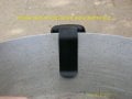
P1030466_Pot_Outside (Side View 640 x 480)).jpg

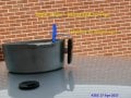
Above is the device clipped to a pot with a "blue" probe (Stainless rod) shown. Questions here include:
1) How can you "Level" the probe? Those colored spacers are glucose tablets.
2) How can you mount the rod.

Commenting on #2. Since it's likely fixed, you can probably get away with an o-ring sliding friction fit or a clamp. multipled

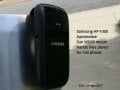
P1030467 (Inside Pot_Clip View 640 x 480).JPG

This image is from inside the pot. So is it too long?

The projection of the clip is about 2-1/8 x 1-1/8", so it might be too long.

You likely can't use the metal itself to make contact to the aluminum pot. It might introduce another contact drop and it's probably spring steel. I've used spring probes from this http://ect-cpg.com/spring-probes company at 200 deg. C. Extremely good life occurred when you did not use high temperature solder, but rather made a mechanical contact.

So, it's just a place to start.

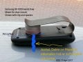
P1030468( Close up Front View 640 x 480)).JPG

In this close-up view I mention the HF device model.

P1030469 (close up - side view 640x480) .JPG


Finally, it's shown "dead bug" style showing the "pot line" as a blue "rod". If the "rod" went through the body and the length was adjustable, then it could "level" the probe horizontally. A lip that sat on the edge of the pot might help too.

Let's pretend that the rod is an insulator like phenolic or PCTFE. There's a nice high temperature plastic PCTFE, http://www.professionalplastics.com/KELF-PCTFERODSHEETTUBE , that will work too. I have some that I was going to use to replace Nylon, because Nylon is unsuitable for my use.

So, now clamp it and move it and set it, your done. Most likele the soup pot is the "soup pot", but then there might be batch sizes.

Now, put one of those spring loaded contacts on it and you have a deal, probably.

I know some home cooks that value their pots as a Picasso. No marks, no matter how slight.

I come from a world where exotics were common place: gallium (a metal that's liquid at room temperature), machinable ceramics, Macor, Boron Nitride, Titanium, gold, Nickel, graphite, platinum, molybdenum, Teflon/PTFE, tungsten, mercury, various grades of steels etc.

PS: I was expecting an answer from my PM about the mechanical filter you want. Do you need more hand-holding there too?
 

Thread Starter

danielj_2016

Joined Jun 24, 2016
85
Hey it's very late so let me just respond quickly to your last question. I believe I had mentioned (maybe not) that I was going to look into that when I renovated the laundry room. My project is to finish the garage resto, which is in midstream right now, then the laundry room is next.

I'll get back to you with comments on the clip for the probe. Maybe I'll take a pic of what I'm using now to get the mv readings. Thanks!
 
Nope, you didn't mention anything about your re-moldeling except you wanted one and I gave some options which depend on your resources and configuration.

==

For all I know, your test adapter could be a couple of OAK rods with notches and a couple of rubber bands (bait bands) and a few alligator clips.

You can make LARGE Hose clamps. We had them at work for 24" diameter. They are like 3 piece. You get ends and a middle that you cut and size. I've spot welded stuff like L-brackets, to the small hose clamps too.
 
Oh good. You confused too. There's a little "backwardsness" going on, I think, as well as some overworked people. It's like the guy that says, build me the electronics for a model gantry crane without the crane. I ran out of posts because WE missed that the loading dock had to have two different positions for load and unload or the mechanical guy makes the contacts sliding so, I really need up/down and off for the crane or he changes the way the two switches interact and expects the software to be unaffected and I thought the first design was better.

I thought our TS/OP (DanielJ). That's Thread Starter / Original Poster needed to create a probe jig - no where near the final product.

keepitsimplestupid said:
alec: Do you have any comments, good or bad about the suggested design?
I'm losing track of where we're at. Do you mean the circuit or the mechanical fixings
At the time of my quote, the only thing on my mind was electrical.

I apologize for throwing a curve ball. I just hit the curve ball Daniel threw with some ideas about anchoring the probe to the pot. Is it a good one, probably not.

So, Daniel needs a lot more hand-holding. "A Heathkit over the Internet!!"

I need to know what I missed? Is it too complicated? etc.
 

Alec_t

Joined Sep 17, 2013
15,159
Is it too complicated? etc.
I would have thought that if a reasonably consistent 0.4V or more can be obtained from an immersed probe plus the aluminium pan then an instrumentation amp is not really justified?
Can't the low-pass filtering be simply a fat cap across probe and pan?
Using two batteries rather than one will make the unit bulky.
IMO trailing wires in a kitchen environment are impractical and unsafe. Accordingly the probe and electronics must be a unitary assembly. That does mean, though, that the assembly needs to be heatproof and have an enclosure with an IP66 rating to withstand steam and hot combustion gases from flames overlapping the pan.
 

Thread Starter

danielj_2016

Joined Jun 24, 2016
85
@kiss and Alec: Yes, I'm completely lost on the electronics, but I have some ideas on the probe end. I do not want to anchor the actual probe to the pot itself. Apologies if I hinted at that. I think early on we discussed the merits of having everything mounted above the pot or on the table with a wire lead. In my mind, given the complexity of housing batteries in a hot, humid, and sometimes acidic environment (vinegar), the easier/cheaper route was to go with a table mounted instrument. In this way, the only parts exposed to the harsh environment are the probe itself (stainless), the mechanism that clamps to the side of the pot, and the wire lead. Yes, it would be nice to have everything "all in one" and kind of cool, but at what cost?

My vision of the clamp is some kind of plastic part that could just be dropped down onto the rim of the pot. I can't post images right now to show what I mean. The part that rests on the rim would have a metal shoe or surface connected to a wire. The wire would go to a connector where you could plug in the lead for the electronics box. The stainless probe itself would be held by another stainless part that would provide the other wire for the connector. Overall if it is made in a durable plastic housing it can be made attractive and small/lightweight.

I think this product would mostly be used for commercial kitchens. There is no concern about damaging the pot by hanging the probe assembly on it. That is a little like saying a carpenter is worried about nicking up his hammer. These pots get scrubbed with metal scrubbies all the time.I also don't have too much concern about the wire. Preferably it would be braided stainless or other durable metal so that there isn't an issue of a plastic sheath melting.

Anyway, it seemed to me when I did the mV testing that the wire choice or length didn't matter. I understand this does not address interference issues. But, my thought is that it doesn't much matter what the "probe" or "probe assembly/clamp" looks like as long as it provides a positive and negative terminal for the electronics.
 
I would have thought that if a reasonably consistent 0.4V or more can be obtained from an immersed probe plus the aluminium pan then an instrumentation amp is not really justified?
Daniel came up with 0.8V. The IA would help with the long leads. CMMR cancelation. Pin selectable gain gives much better CMMR.

Can't the low-pass filtering be simply a fat cap across probe and pan?
In inherently, the DVM does th LP filtering with the dual-slope conversion technique. Daniel can't see the 60 Hz noise. I did an experiment and reported it somewhere in this thread, where a dangling unshielded wire to a scope with a 1 M input picks up significant chatter. So, I don't think so.

In my professional life, we had unshielded cables going to an X-Y recorder with likely the same sort of input. The carriage would definitely make a lot of noise when unconnected. The device has a low impedance usually. Those tests were OK.

AT one point, we installed a passive low-pass filter and it was the size of a cigar box.

Using two batteries rather than one will make the unit bulky
Am planning a single 9V battery. The 5V is for debugging only. The filter and the IA was difficult to do at less than 3V or as a CR2032 discharged. Long battery life generally means low-voltage and loud buzzer means a higher voltage/power.

There's a lot of tradeoffs.


IMO trailing wires in a kitchen environment are impractical and unsafe. Accordingly the probe and electronics must be a unitary assembly. That does mean, though, that the assembly needs to be heatproof and have an enclosure with an IP66 rating to withstand steam and hot combustion gases from flames overlapping the pan.
A pot of soup where the leads can "fly off" easily isn't too bad.

Not knocking those requirements at all. The buzzer, I think, is the killer and won't have much life there. Early thoughts included a DXS alarm transmitter used in commercial alarm systems. They have battery supervision.[/quote][/quote]
 
Last edited:
Using two batteries rather than one will make the unit bulky.
@kiss and Alec: Yes, I'm completely lost on the electronics, but I have some ideas on the probe end. I do not want to anchor the actual probe to the pot itself. Apologies if I hinted at that. I think early on we discussed the merits of having everything mounted above the pot or on the table with a wire lead. In my mind, given the complexity of housing batteries in a hot, humid, and sometimes acidic environment (vinegar), the easier/cheaper route was to go with a table mounted instrument. In this way, the only parts exposed to the harsh environment are the probe itself (stainless), the mechanism that clamps to the side of the pot, and the wire lead. Yes, it would be nice to have everything "all in one" and kind of cool, but at what cost?
"Anchor" is a bad word. That's where wireless and "pot-centric" mean good things. The buzzer and the 9V battery aren't the greatest.

My vision of the clamp is some kind of plastic part that could just be dropped down onto the rim of the pot. I can't post images right now to show what I mean. The part that rests on the rim would have a metal shoe or surface connected to a wire. The wire would go to a connector where you could plug in the lead for the electronics box. The stainless probe itself would be held by another stainless part that would provide the other wire for the connector. Overall if it is made in a durable plastic housing it can be made attractive and small/lightweight.
A lot of the safety depends on cutting the probe. How far it extends above the pot impacts safety. So, I came up wit something that removes easily. Breakaway would be better yet.

I think this product would mostly be used for commercial kitchens. There is no concern about damaging the pot by hanging the probe assembly on it. That is a little like saying a carpenter is worried about nicking up his hammer. These pots get scrubbed with metal scrubbies all the time.I also don't have too much concern about the wire. Preferably it would be braided stainless or other durable metal so that there isn't an issue of a plastic sheath melting.
Yippee. I "cat sat" for this person who had major concerns about her cookware. Her parents had lots of money.

Anyway, it seemed to me when I did the mV testing that the wire choice or length didn't matter. I understand this does not address interference issues. But, my thought is that it doesn't much matter what the "probe" or "probe assembly/clamp" looks like as long as it provides a positive and negative terminal for the electronics.
Your tests won't because of how a DVM works.
 

AD8231 footprint to DIP

This http://www.proto-advantage.com/store/product_info.php?products_id=3150007 adapter will fit the AD8231 Instrumentation amplifier
Now we need the full p/n including the digikey part.
Looks like you need the -EP version which is OK, but more expensive if
you want proto-advantage to mount the part.
Digikey p/n: AD8231TCPZ-EP-R7CT-ND
from: https://www.digikey.com/product-det...D8231TCPZ-EP-R7/AD8231TCPZ-EP-R7CT-ND/3767249

The non EP version is available elsewhere. 1/3 cheaper https://www.avnet.com/shop/us/p/amp...7345626891556?CMP=NA-US-NEWARK-PDP-CROSS-SELL

REF2030 footprint (SOT-23) to DIP
http://www.proto-advantage.com/store/product_info.php?products_id=2200093
Digi-key p/n: of 296-38496-1-ND
https://www.digikey.com/product-detail/en/texas-instruments/REF2030AIDDCT/296-38496-1-ND/5023888

LT6700-1 footprint (SOT-23) to DIP
Digikey p/n: LT6700HVCS6-3#TRMPBFCT-ND

http://www.proto-advantage.com/store/product_info.php?products_id=2200093
 
Last edited:
I updated the Digi-key part numbers for the 3 major parts. You can place a proto-advantage order to get DIP adapters for the major parts.

Another construction technique would be a thru-hole board (I have bias toward ones with square pads)

You can use these: http://www.proto-advantage.com/store/product_info.php?products_id=1900006 and cut them for the various parts including the IC's. Getting the adapters with "square pins" would be the way to go if you wanted to use the above sockets.

You could also buy these http://www.proto-advantage.com/store/product_info.php?products_id=3700004 UNASSEMBLED and use it for practice for the 1206 resistors.

The Ad8231, I don't recommend even trying to solder that part yet. I like 63/37 wire solder, but it contains lead. They have the 42/57 solder paste which I really like and they have 63/37 in paste form too. The kits contain a fair amount of solder paste.

Warning: Solder paste has a short shelf life, but for one-of quantities it doesn't matter as much. It should be stored refrigerated. I know a really good source of HDPE jars that have lids that really seal.

This http://www.proto-advantage.com/store/product_info.php?products_id=2210093 isn't a bad kit to get your feet wet and try to solder the other SOT 23-5 parts.

Their videos pretty much show you what you have to do to assemble an adapter. A PCB positioner is used to position the pins before soldering.

The part depending on what it is and the quantity, you basically line up the stencil and squeegee the paste to the pads, remove the stencil place the part and heat.

There is stuff that can be use to "tack" components before soldering. That stuff is designed that when you twist, the bond breaks.
 
Selecting the 100 nF capacitors for the Filter in the Probe_Conditioning, I get this: https://www.digikey.com/product-detail/en/kemet/LDECB3100JA0N00/399-6413-1-ND/3028771

So, a 100 nF cap is a 0.1 uF capacitor https://www.digikey.com/product-detail/en/kemet/LDECB3100JA0N00/399-6413-1-ND/3028771, and +-5% seems reasonable since this is a filter. You can pick either 1% or 5% resistors in the filter area.

It turns out that this part is a 1210 and not a 1206, so it's a little wider. It would still fit on a 1206 breakout.

This https://www.digikey.com/product-det...ceramics/200B104KT50XT/1284-1471-1-ND/5767938 will work for the low ESR caps on the 3/1.5 regulator. Price, but you can grab them. They are a 1211 size and not 1206. They might fit on a 1206 breadboard.

They may recommend a cap in the datsheet. So, ceramic, low ESR and 0.1 uF is important.
The voltage has to be at least 2x the working voltage. The lower the voltage, the smaller the cap.
1211 is much easier to grab. At this stage,let's use the 1211. This could be an example of using the SMT headers where you might be able to evaluate different capacitors just by plugging them in. So, here the 2x in price at this stage is offset by the ability to be able to pick them up.

Here https://www.digikey.com/product-det...rica/LLM315R71C104MA11L/490-4495-1-ND/1022639 is a 1206 0.1 uf ceramic capacitor for general bypassing. See note 5.

For a 1 uF electrolytic cap, this https://www.digikey.com/product-det...c-components/EEE-FC1V1R0R/PCE4024CT-ND/817486 will work. Note 4.

This https://www.digikey.com/product-detail/en/avx-corporation/F931C105MAA/478-8234-2-ND/4004967 could work. Tantalum 1206. Note 4.
Tantalum is an electrolytic capacitor that really hates to installed backwards even momentarily. Early versions of this type had problems.
Note 4.

Sol Alec's comment of being expensive turns out to be true. Quality doesn't come cheap either. Cost comes down when manufactured overseas and quantity goes up.

There's really about two companies in the linear IC circuit business now. Texas Instruments (TI) and Analog Devices. Linear Technology just got bought by AD. I was looking at other IA's and the AD part still seems the best.

If you want to use a typical micro USB cell phone charger, then a MicroUSB breakout is in order. See: https://www.digikey.com/products/en...pter-breakout-boards/643?k=micro usb breakout I'd get the one that's labeled. The USB adapter should supply 100 mA without anything fancy.

On the surface, it seems so simple, You still have Alec's circuit too. There is all sorts of things competing against each other.

I'm even looking at this from a prototyping at the end of a long lineage starting from the tube or valve era. Parts lifetime isn't infinite. A whole bunch of parts just got tossed because of the ROHS directive of the European Union. There are two antique NTSC TV's in the house that had a channel #1 on them. The now lack of leads (thru-hole parts) tossed another lot.

I should mention that SMT parts have an MSL or Moisture Sensitivity Level which puts a "shelf life" on the parts. Yes, electronic parts now have a shelf life. A baking cycle brings them back to life or back to being able to be machine soldered.
 
Last edited:
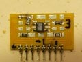
This is probably one of my very first SMT breadboards. It used a Digi-Key part that allowed more than just the IC to be mounted,
There are 0 ohm resistors (SMT jumpers) used too. There is a tiny LED by the smudge and it uses a similar relay module to the one I used for your water alarm. I used wire solder, I think.

Breadboard (640x480).jpg
 
daniel:

Here's https://www.allaboutcircuits.com/pr...s-hot-air-soldering-surface-mount-components/ an article just posted on AAC.

The only thing I disagree with is using 60/40 solder. 63/37 is much better for SMT stuff. Both contain lead.

With 63/27 the solidus and liquidus points are the same. That means it melts and solidifies at the same temperature which works to your advantage.

The VERY FIRST SMT device I removed and replaced was a fine pitched CPU with at least 40 pins in a car radio. It was done with a non-temperature controlled iron and 63/37 wire solder.
 

Thread Starter

danielj_2016

Joined Jun 24, 2016
85
Thanks KISS for the link to soldering. That's very helpful. So I have to buy a hot air gun in order to do this properly?

I have something and I wonder if it can be used somehow for this project. Years ago I needed to solder two pieces of brass together by dipping them in solder. I bought a little heated well and melted a spool of lead free solder in the well. I would paint the brass in flux and then dip them in the well, which seemed to work despite the brass not being preheated. Anyway I have this well full of solder in the basement. It's actually a pretty rugged looking piece of equipment. I wonder if there is any way to make use of this (dipping the connectors into the solder?) since I already have it. Anybody use one for a project like this?
 
Top