Gate drive of SMPS with one gate needing negative voltage to switch off.

Thread Starter

farm_tinker

Joined Nov 20, 2025
37
I've been working on this for several months and am about ready to solder up my first test circuit of the power section, my control firmware is producing a nice tight pair of square waves. Topology is an inverting buck-boost. I really want to use a MOSFET as a rectifier instead of a Schottky for the efficiency as this is powered from a single lihtium cell.

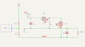
Minimal circuit:
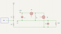
1790875646126.png

Q1 will see voltages on the order of 10V:
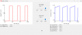
1790875713958.png

Q2 will see voltages on the order of -10V:
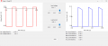
1790875792050.png

MOSFETs are logic level Toshiba SSM6K804R,LF. I don't have to use these MOSFETs but they should do the job.

Control signals are 5V square, 315kHz, 50ns deadtime:
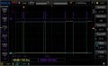
startup square.jpg


How do I drive the gates of both MOSFETs at these speeds and voltages?

There are all sorts of gate drivers that will handle Q1. However, for Q2, either I don't know the right term or what I'm looking for isn't available. I've read about negative charge pumps and a little about Third Quadrant but I don't know what I'm looking for.

My first test circuit of this part of the design is going to be hand soldered SMD on a proto board. I have little experience soldering SMD. While I could put a Schottky in instead of a MOSFET for Q2, I'd really prefer to go with something closer to my final design and only proto board it once. Final version will be a PCB.

Any suggestions for a drive IC or research topic would be greatly appreciated!
 

ronsimpson

Joined Oct 7, 2019
4,851
One of the hard things to teach is that MOSFETS do not know or care where ground is. They do not know what the Gate voltage is. They only care what the Gate to Source voltage is.
1790877965576.png
Q2 has a Source that has a voltage from near Ground to -10V. So the gate driver needs to stand on Vout.
Q1 has a Source that could be at Vin or as negative as Vout. So the Gate driver needs to stand on Q1 Source.

It appears you have 2.8V and 5V. Where does the 5V come from?
 

ronsimpson

Joined Oct 7, 2019
4,851
Have you thought about using two batteries to get the voltage up to 2.8x2=5.6V. Now do a buck PWM and there is no negative voltage.
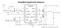
There are some low voltage sync. buck PWMs. In the data sheet they show a buck for 10A. Because you have a micro you can measure current X measure voltage and then tell the PWM to increase/decrease the duty cycle. This is probably less parts than finding a gate driver that will work.
1790883522679.png
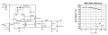
Here is another example. Change the MOSFETs to lower RDSon and get more current. I think I can find some with the MOSFETs inside the IC.
1790883892255.png
 

Thread Starter

farm_tinker

Joined Nov 20, 2025
37
It appears you have 2.8V and 5V. Where does the 5V come from?
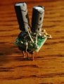
MCP1640D switch mode IC. I didn't have low ESR ceramics onhand when I put this ugly test DIP together, but it runs just fine with big old electrolytics. It's the Little Engine that Could. I've been impressed.

KIMG20261001_165716928.JPG

Have you thought about using two batteries to get the voltage up to 2.8x2=5.6V.
Two batteries mean that it will not hit the same form factor. It won't ride in my shirt pocket the same way and my wife likely would not accept it. There's another lithium like the 18650 that's shorter, I might could series two of them, but I really don't want to.

KIMG20261001_170358628.JPG


KIMG20261001_170529937.JPG

If I insist on a single cell, you think I'm stuck going with a Schottky instead of Q2?
 

kiroma

Joined Apr 30, 2014
294
Some tips:
Post the whole schematic, explain which source is what type.
Resize the photos/images you post to a somewhat good amount. It doesn't need to not even fit in the screen of a laptop because it's so big.
 

kiroma

Joined Apr 30, 2014
294
How do I drive the gates of both MOSFETs at these speeds and voltages?

There are all sorts of gate drivers that will handle Q1. However, for Q2, either I don't know the right term or what I'm looking for isn't available. I've read about negative charge pumps and a little about Third Quadrant but I don't know what I'm looking for.
With transformers is a well known practice.
With bootstrap capacitor is a small factor form solution.
 

Thread Starter

farm_tinker

Joined Nov 20, 2025
37
Some tips:
Post the whole schematic, explain which source is what type.
Resize the photos/images you post to a somewhat good amount. It doesn't need to not even fit in the screen of a laptop because it's so big.
Sorry about the giant images. (They didn't seem that big on my computer) :)
This thread contains schematic and goes into detail about the circuit.

I Also would suggest gate drive transformers.
Currently, plan is to use a SI8273GB-IS1 so I can play with the PWM I managed to squeeze out of the ATtiny 3224. Final will probably be a TI TPS28225 as it will save me another pin.
 
Top