New relay switch setup for two heat pumps and one shared well pump

Thread Starter

LaRob

Joined Dec 24, 2024
2
I have two heat pumps in my house, one for downstairs and one for upstairs. Each unit had a wire that ran from C and G wires on the AC to a relay box setup on the side of the house so either unit could activate the well pump. One AC unit was recently replaced and the installers disconnected the relay wire and terminated it somewhere in a wall that I cannot find and the tech that worked on it doesn't work there anymore. We also remodeled since the unit was replaced and I think the electricians may have taken the wire out when they couldn't trace it.

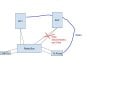
The water pump pumps water through both units no matter which is on, so i just need a way for either unit to turn on the pump again. I have no way to get a new wire down to the relay box, but I can access both AC units in the attic to setup a relay between the two of them and then use the existing wire to send another signal to the relay box.

My question: What kind of relay setup would I need between the two AC units to send a control signal down the wire to the relay on the well pump? I imagine an OR gate with relays in parallel, but I'm not really familiar with the options. I would have each unit energize the relay based on the fan terminal. Rough sketch is attached. Thanks in advance.
 

Attachments

Tonyr1084

Joined Sep 24, 2015
9,744
Welcome to AAC.
This just may be a problem that needs to be solved by a professional. For us to know what is going on in your house is impossible. The best we could do is probably guess at a solution. And the description of your issues does not provide enough clarity for - well - for 'me' to follow. Don't know about others, but I suspect they'll be feeling the same way.

The best way to get a good answer is to provide a schematic. It's the brail of electronics. We can read it and understand it without words.
 

Thread Starter

LaRob

Joined Dec 24, 2024
2
I understand your concern- we have an old open loop geothermal system that no one around here does anymore so no one understands the entire system setup. No trade will touch the entire system, just the different components. I need a plan that I can give to either the AC company, the electrician or a plumber to have them implement.

I need either AC unit to be able to send a control signal to a third relay that controls the pump.
 

crutschow

Joined Mar 14, 2008
38,323
If I understand correctly, you could add two AC coil relays, (SPST or SPDT) and use the ON voltage from the HP units to control each relay's coil.
The NO contacts from the two relays would be connected to the AC in parallel to control the water pump (providing the OR gate function).
Thus the pump would come on if either (or both) of the HP units is on. (Schematic below):

1735053853563.png
 
Last edited:

LesJones

Joined Jan 8, 2017
4,511
crutschow, It might be worth confirming that the signal on the C & G wiries is mains voltage. I tried to find information on the C & G wires but did not find anything helpful. I agree with your suggestion of using two relays as the TS seems to say that both AC uints are close together. I suspect the original external relay box was just 2 relays in the same configuration that you suggest
The TS could could check the voltage (And if it is AC or DC.) on the C & G wires from AC1 Or post a picture of the inside of the original relay box to see if it is just two relays. One of the original relay would still be used to switch the current used by the pump
Les.
 

MisterBill2

Joined Jan 23, 2018
27,186
It gets a bit more complicated than has been presented because with central AC systems there is an internal 24 volt power transformer inside the compressor unit. Those are the ones that have two red wires connected at the thermostat, mostly. In the other, more common arrangements, there is only one 24 volt AC source, based on never needing to power the heating gas valve and the cooling compressor contactor at the same time.
As for telling if the control connection is 24 volts or mains power, the wiring for the two is vastly different in every system that meets the basic electrical code. Mains voltage wiring always is protected and always has the higher voltage insulation, and is either #14 or #12 wire. 24 volt wiring is always much thinner conductors and has thinner insulation, and the wire runs do not have secondary protective layers. The easy way to determine the scheme is to measure the control terminals connection while the power is on but the compressor is not running. If the voltage is around 24 volts, the unit has an internal transformer, if it is zero when the unit is off, and 24 volts when it is running, then the system has only one common transformer. This is the most common scheme. For that, the simple connection is a 24 volt relay across each of the control connections, and then the contacts of each relay connected in parallel to start the well pump.
 
Top